TITLE 13. HOUSING
REGISTRAR'S NOTICE: The Board of Housing and Community Development is claiming an exemption from Article 2 of the Administrative Process Act pursuant to § 2.2-4006 A 12 of the Code of Virginia, which excludes regulations adopted by the board pursuant to the Statewide Fire Prevention Code (§ 27-94 et seq.), the Industrialized Building Safety Law (§ 36-70 et seq.), the Uniform Statewide Building Code (§ 36-97 et seq.), and § 36-98.3 of the Code of Virginia, provided the board (i) provides a Notice of Intended Regulatory Action in conformance with the provisions of § 2.2-4007.01, (ii) publishes the proposed regulation and provides an opportunity for oral and written comments as provided in § 2.2-4007.03, and (iii) conducts at least one public hearing as provided in §§ 2.2-4009 and 36-100 prior to the publishing of the proposed regulations. The Board of Housing and Community Development will receive, consider, and respond to petitions regarding 13VAC5-63-210 by any interested person at any time with respect to reconsideration or revision.
Title of Regulation: 13VAC5-63. Virginia Uniform Statewide Building Code (amending 13VAC5-63-210).
Statutory Authority: § 36-98 of the Code of Virginia.
Public Hearing Information:
September 28, 2020 - 10 a.m. - Google Meet Meeting - The link to access the electronic meeting is meet.google.com/rqj-cmsq-rft, or copy and paste the link into a browser. Additional details and information are available on the Virginia Regulatory Town Hall (www.townhall.virginia.gov).
Public Comment Deadline: November 13, 2020.
Agency Contact: Kyle Flanders, Senior Policy Analyst, Department of Housing and Community Development, Main Street Centre, 600 East Main Street, Suite 300, Richmond, VA 23219, telephone (804) 786‑6761, FAX (804) 371‑7090, TTY (804) 371‑7089, or email kyle.flanders@dhcd.virginia.gov.
Background: The Uniform Statewide Building Code (USBC) is a regulation governing the construction, maintenance, and rehabilitation of new and existing building and structures. The USBC uses nationally recognized model building codes and standards produced by the International Code Council (ICC) and other standard-writing groups as the basis for the technical provisions of the regulation. Every three years, new editions of the model codes become available. At that time, the Board of Housing and Community Development (BHCD) initiates a regulatory action to incorporate the newest editions of the model codes into the regulation as well as accepting proposals for changes to the regulation from affected client groups and the public.
This proposed phase of the regulatory action only includes 13VAC5-63-210. The text of this section was published correctly in the Virginia Register of Regulations in Volume 36, Issue 12 on February 3, 2020. However, due to a technical error, certain information may not have been present on the Virginia Regulatory Town Hall website -- specifically, 13VAC5-63-210.
Summary:
The proposed substantive amendments to 13VAC5-63-210 do the following:
1. Make several changes to the Residential Code, including updating REScheck to the 2018 International Energy Conservation Code (IECC).
2. Eliminate the deletion of the energy certificate requirement and revise the section to allow the certificate to be kept at an offsite location for multifamily buildings.
3. Remove visual option and require blower door testing for air leakage rate of buildings (5 air changes).
4. Remove prohibition against using building cavities as plenums.
5. Remove the requirement for residential exhaust hoods in kitchens for grease laden vapors as the requirements for this are specified in the International Mechanical Code and do not belong in the IECC.
6. Revise landing/floor height requirement for exterior doors from to 8-1/4 inches.
7. Allow the use of Appendix Q for tiny houses (i.e., dwellings 400 square feet or less).
8. Revise foundation anchorage language to match the International Building Code.
9. Clarify that only one foundation vent is required within three feet of each corner.
10. Add an option for relining existing building sewers and building draining piping.
11. Add an option to provide a notice by electronic means for a local board of building code appeals hearing.
12. Change the minimum slope from two percent to one percent for drainage on impervious surfaces within 10 feet of the building foundation.
Other proposed changes update citations to incorporated codes and statutes, reorganize standards for a more appropriate placement in the code, or clarify or correlate provisions.
13VAC5-63-210. Chapter 3 Use and occupancy classification.
A. Change Sections 303.1.1 and 303.1.2 of the IBC to read:
303.1.1 Small buildings and tenant spaces. A building or tenant space used for assembly purposes with an occupant load of less than 50 persons shall be permitted to be classified as a Group B occupancy.
303.1.2 Small assembly spaces. The following rooms and spaces shall be permitted to be classified as Group B occupancies or as part of the assembly occupancy:
1. A room or space used for assembly purposes with an occupant load of less than 50 persons and ancillary to another occupancy.
2. A room or space used for assembly purposes that is less than 750 square feet (70 m2) in area and ancillary to another occupancy.
B. Change Section 303.6 of the IBC to read:
303.6 Assembly Group A-5. Assembly uses intended for participation in or viewing outdoor activities including, but not limited to:
Amusement park structures
Bleachers
Grandstands
Stadiums
Swimming pools
C. Add Section 304.1.1 to the IBC to read:
304.1.1 Day support and day treatment facilities. Day support and day treatment facilities licensed by the Virginia Department of Behavioral Health and Developmental Services shall be permitted to be classified as Group B occupancies provided all of the following conditions are met:
1. Participants who may require physical assistance from staff to respond to an emergency situation shall be located on the level of exit discharge.
2. Any change in elevation within the exit access on the level of exit discharge shall be made by means of a ramp or sloped walkway.
3. Where the facilities are located more than two stories above grade, an automatic sprinkler system shall be provided throughout the building in accordance with Section 903.3.1.1.
D. Change exception Exception 14 of Section 307.1.1 of the IBC and add exception 15 Exception 18 to Section 307.1.1 of the IBC to read:
14. The storage of black powder, smokeless propellant and small arms primers in Groups M, R-3 and R-5 and special industrial explosive devices in Groups B, F, M and S, provided such storage conforms to the quantity limits and requirements prescribed in the IFC, as amended in Section 307.9.
15. 18. The storage of distilled spirits and wines in wooden barrels and casks. Distillation, blending, bottling, and other hazardous materials storage or processing shall be in separate control areas complying with Section 414.2.
E. Change the "Flammable liquid, combination (IA, IB, IC)" row in Table 307.1(1), add a new "Permissible fireworks" row to Table 307.1(1) of the IBC, and add footnote "r" to Table 307.1(1) of the IBC to read:
Flammable liquid, combination (IA, IB, IC) | NA | H-2 or H-3 | NA | 120d,e,h | NA | NA | 120d,h | NA | NA | 30d,h,r |
Permissible fireworks | 1.4G | H-3 | 125d,e,l | NA | NA | NA | NA | NA | NA | NA |
r. The tabular value for distilled spirit distillation and blending rooms is 120 gallons. |
F. Add Section 307.9 to the IBC to read:
307.9 Amendments. The following changes shall be made to the IFC for the use of Exception 14 in Section 307.1.1:
1. Change the following definition in Section 202 of the IFC to read:
Smokeless propellants. Solid propellants, commonly referred to as smokeless powders, or any propellants classified by DOTn as smokeless propellants in accordance with NA3178 (Smokeless Powder for Small Arms), used in small arms ammunition, firearms, cannons, rockets, propellant-actuated devices, and similar articles.
2. Change Section 314.1 of the IFC to read as follows:
314.1 General. Indoor displays constructed within any building or structure shall comply with Sections 314.2 through 314.5.
3. Add new Section 314.5 to the IFC to read as follows:
314.5 Smokeless powder and small arms primers. Vendors shall not store, display or sell smokeless powder or small arms primers during trade shows inside exhibition halls except as follows:
1. The amount of smokeless powder each vender may store is limited to the storage arrangements and storage amounts established in Section 5606.5.2.1.
2. Smokeless powder shall remain in the manufacturer's original sealed container and the container shall remain sealed while inside the building. The repackaging of smokeless powder shall not be performed inside the building. Damaged containers shall not be repackaged inside the building and shall be immediately removed from the building in such manner to avoid spilling any powder.
3. There shall be at least 50 feet separation between vendors and 20 feet from any exit.
4. Small arms primers shall be displayed and stored in the manufacturer's original packaging and in accordance with the requirements of Section 5606.5.2.3.
4. Change Exception 4 and add Exceptions 10 and 11 to Section 5601.1 of the IFC as follows:
4. The possession, storage and use of not more than 15 pounds (6.75 kg) of commercially manufactured sporting black powder, 20 pounds (9 kg) of smokeless powder and any amount of small arms primers for hand loading of small arms ammunition for personal consumption.
10. The display of small arms primers in Group M when in the original manufacturer's packaging.
11. The possession, storage and use of not more than 50 pounds (23 kg) of commercially manufactured sporting black powder, 100 pounds (45 kg) of smokeless powder, and small arms primers for hand loading of small arms ammunition for personal consumption in Group R-3 or R-5, or 200 pounds (91 kg) of smokeless powder when stored in the manufacturer's original containers in detached Group U structures at least 10 feet (3048 mm) from inhabited buildings and are accessory to Group R-3 or R-5.
5. Change Section 5606.4 of the IFC to read as follows:
5606.4 Storage in residences. Propellants for personal use in quantities not exceeding 50 pounds (23 kg) of black powder or 100 pounds (45 kg) of smokeless powder shall be stored in original containers in occupancies limited to Group Groups R-3 and R-5 or 200 pounds (91 kg) of smokeless powder when stored in the manufacturer's original containers in detached Group U structures at least 10 feet (3048 mm) from inhabited buildings and are accessory to Group R-3 or R-5. In other than Group R-3 or R-5, smokeless powder in quantities exceeding 20 pounds (9 kg) but not exceeding 50 pounds (23 kg) shall be kept in a wooden box or cabinet having walls of at least one inch (25 mm) nominal thickness or equivalent.
6. Delete Sections 5606.4.1 and 5606.4.2 of the IFC.
7. Change Section 5606.5.1.1 of the IFC to read as follows:
5606.5.1.1 Smokeless propellant. No more than 100 pounds (45 kg) of smokeless propellants in containers of eight pounds (3.6 kg) or less capacity shall be displayed in Group M occupancies.
8. Delete Section 5606.5.1.3 of the IFC.
9. Change Section 5606.5.2.1 of the IFC as follows:
5606.5.2.1 Smokeless propellant. Commercial stocks of smokeless propellants shall be stored as follows:
1. Quantities exceeding 20 pounds (9 kg), but not exceeding 100 pounds (45 kg) shall be stored in portable wooden boxes having walls of at least one inch (25 mm) nominal thickness or equivalent.
2. Quantities exceeding 100 pounds (45 kg), but not exceeding 800 pounds (363 kg), shall be stored in storage cabinets having walls at least one inch (25 mm) nominal thickness or equivalent. Not more than 400 pounds (182 kg) shall be stored in any one cabinet, and cabinets shall be separated by a distance of at least 25 feet (7620 mm) or by a fire partition having a fire-resistance rating of at least one hour.
3. Storage of quantities exceeding 800 pounds (363 kg), but not exceeding 5,000 pounds (2270 kg) in a building shall comply with all of the following:
3.1. The warehouse or storage room is inaccessible not open to unauthorized personnel.
3.2. Smokeless propellant shall be stored in nonportable storage cabinets having wood walls at least one inch (25 mm) nominal thickness or equivalent and having shelves with no more than 3 feet (914 mm) of vertical separation between shelves.
3.3. No more than 400 pounds (182 kg) is stored in any one cabinet.
3.4. Cabinets shall be located against walls with at least 40 feet (12 192 (12,192 mm) between cabinets. The minimum required separation between cabinets may be reduced to 20 feet (6096 mm) provided that barricades twice the height of the cabinets are attached to the wall, midway between each cabinet. The barricades must extend a minimum of 10 feet (3048 mm) outward, be firmly attached to the wall, and be constructed of steel not less than 0.25 inch thick (6.4 mm), 2-inch (51 mm) nominal thickness wood, brick, or concrete block.
3.5. Smokeless propellant shall be separated from materials classified as combustible liquids, flammable liquids, flammable solids, or oxidizing materials by a distance of 25 feet (7620 mm) or by a fire partition having a fire-resistance rating of 1 hour.
3.6. The building shall be equipped throughout with an automatic sprinkler system installed in accordance with Section 903.3.1.1.
4. Smokeless propellants not stored according to Item 1, 2, or 3 above shall be stored in a Type 2 or 4 magazine in accordance with Section 5604 and NFPA 495.
G. Add the following to the list of terms in Section 308.2 of the IBC:
Hospice facility
H. G. Change Section 308.3 308.2 of the IBC to read:
308.3 308.2 Institutional Group I-1. This occupancy shall include buildings, structures or portions thereof for more than 16 persons, excluding staff, who reside on a 24-hour basis in a supervised environment and receive custodial care. Buildings of Group I-1, other than assisted living facilities licensed by the Virginia Department of Social Services, shall be classified as the occupancy condition indicated in Section 308.3.1 308.2.1. Assisted living facilities licensed by the Virginia Department of Social Services shall be classified as one of the occupancy conditions indicated in Section 308.3.1 308.2.1 or 308.3.2 308.2.2. This group shall include, but not be limited to, the following:
Alcohol and drug centers
Assisted living facilities
Congregate care facilities
Group homes
Halfway houses
Residential board and care facilities
Social rehabilitation facilities
I. H. Change Sections 308.3.1 308.2.1 and 308.3.2 308.2.2 of the IBC to read:
308.3.1 308.2.1 Condition 1. This occupancy condition shall include buildings in which all persons receiving custodial care who, without any assistance, are capable of responding to an emergency situation to complete building evacuation. Not more than five of the residents may require physical assistance from staff to respond to an emergency situation when all residents who may require the physical assistance reside on a single level of exit discharge.
308.3.2 308.2.2 Condition 2. This occupancy condition shall include buildings in which there are persons receiving custodial care who require assistance by not more than one staff member while responding to an emergency situation to complete building evacuation. Five of the residents may require physical assistance from more than one staff member to respond to an emergency.
J. I. Change Section 308.4 308.3 of the IBC to read:
308.4 308.3 Group I-2. This occupancy shall include buildings and structures used for medical care on a 24-hour basis for more than five persons who are incapable of self-preservation. This group shall include, but not be limited to, the following:
Convalescent facilities
Detoxification facilities
Foster care facilities
Hospice facilities
Hospitals
Nursing homes
Psychiatric hospitals
Exception: Hospice facilities occupied by 16 or less occupants, excluding staff, are permitted to be classified as Group R-4.
K. J. Add an exception to Section 308.6 308.5 of the IBC to read:
Exception: Family day homes under Section 310.9 310.8.
L. K. Change Section 310.3 310.2 of the IBC to read:
310.3 310.2 Residential Group R-1. Residential occupancies containing sleeping units where the occupants are primarily transient in nature, including:
Boarding houses (transient) with more than 10 occupants
Congregate living facilities (transient) with more than 10 occupants
Hotels (transient)
Motels (transient)
Exceptions:
1. Nonproprietor occupied bed and breakfast and other transient boarding facilities not more than three stories above grade plane in height with a maximum of 10 occupants total are permitted to be classified as either Group R-3 or R-5 provided that smoke alarms are installed in compliance with Section 907.2.11.2 907.2.10.2 for Group R-3 or Section R314 of the IRC for Group R-5.
2. Proprietor occupied bed and breakfast and other transient boarding facilities not more than three stories above grade plane in height, that are also occupied as the residence of the proprietor, with a maximum of five guest room sleeping units provided for the transient occupants are permitted to be classified as either Group R-3 or R-5 provided that smoke alarms are installed in compliance with Section 907.2.11.2 907.2.10.2 for Group R-3 or Section R314 of the IRC for Group R-5.
M. L. Change Section 310.6 310.5 of the IBC to read:
310.6 310.5 Residential Group R-4. This occupancy shall include buildings, structures or portions thereof for more than five but not more than 16 persons, excluding staff, who reside on a 24-hour basis in a supervised environment and receive custodial care. Buildings of Group R-4, other than assisted living facilities licensed by the Virginia Department of Social Services, shall be classified as the occupancy condition indicated in Section 310.6.1 310.5.1. Assisted living facilities licensed by the Virginia Department of Social Services shall be classified as one of the occupancy conditions indicated in Section 310.6.1 310.5.1 or 310.6.2 310.5.2. This group shall include, but not be limited to the following:
Alcohol and drug centers
Assisted living facilities
Congregate care facilities
Group homes
Halfway houses
Residential board and care facilities
Social rehabilitation facilities
This occupancy shall also include hospice facilities with not more than 16 occupants, excluding staff.
Group R-4 occupancies shall meet the requirements for construction as defined for Group R-3, except as otherwise provided for in this code.
Exceptions:
1. Group homes licensed by the Virginia Department of Behavioral Health and Developmental Services that house no more than eight persons with one or more resident counselors shall be classified as Group R-2, R-3, R-4 or R-5. Not more than five of the persons may require physical assistance from staff to respond to an emergency situation.
2. In Group R-4 occupancies classified as the occupancy condition indicated in Section 310.6.1 310.5.1, other than in hospice facilities, not more than five of the residents may require physical assistance from staff to respond to an emergency situation when all residents who may require the physical assistance from staff reside on a single level of exit discharge and other than using a ramp, a change of elevation using steps or stairs is not within the path of egress to an exit door.
3. Assisted living facilities licensed by the Virginia Department of Social Services that house no more than eight persons, with one or more resident counselors, and all of the residents are capable of responding to an emergency situation without physical assistance from staff, may be classified as Group R-2, R-3 or R-5.
4. Assisted living facilities licensed by the Virginia Department of Social Services that house no more than eight persons, with one or more resident counselors, may be classified as Group R-5 when in compliance with all of the following:
4.1. The building is protected by an automatic sprinkler system installed in accordance with Section 903.3 or Section P2904 of the IRC.
4.2. Not more than five of the residents may require physical assistance from staff to respond to an emergency situation.
4.3. All residents who may require physical assistance from staff to respond to an emergency situation reside on a single level of exit discharge and other than using a ramp, a change in elevation using steps or stairs is not within the path of egress to an exit door.
5. Hospice facilities with five or fewer occupants are permitted to comply with the IRC provided the building is protected by an automatic sprinkler system in accordance with IRC Section P2904 or IBC Section 903.3.
N. M. Change Sections 310.6.1 310.5.1 and 310.6.2 310.5.2 to the IBC to read:
310.6.1 310.5.1 Condition 1. This occupancy condition shall include buildings in which all persons receiving custodial care who, without any assistance, are capable of responding to an emergency situation to complete building evacuation and hospice facilities.
310.6.2 310.5.2 Condition 2. This occupancy condition shall include buildings in which there are persons receiving custodial care who require assistance by not more than one staff member while responding to an emergency situation to complete building evacuation.
O. N. Add Section 310.7 310.6 to the IBC to read:
310.7 310.6 Residential Group R-5. Residential occupancies in detached single-family and two-family dwellings, townhouses and accessory structures within the scope of the IRC.
P. O. Add Section 310.8 310.7 to the IBC to read:
310.8 Group R-5. The construction of Group R-5 structures shall comply with the IRC. The amendments to the IRC set out in Section 310.11 310.10 shall be made to the IRC for its use as part of this code. In addition, all references to the IRC in the IBC shall be considered to be references to this section.
Q. P. Add Section 310.8.1 310.7.1 to the IBC to read:
310.8.1 310.7.1 Additional requirements. Methods of construction, materials, systems, equipment or components for Group R-5 structures not addressed by prescriptive or performance provisions of the IRC shall comply with applicable IBC requirements.
R. Q. Add Section 310.9 310.8 to the IBC to read:
310.9 310.8 Family day homes. Family day homes where program oversight is provided by the Virginia Department of Social Services shall be classified as Group R-2, R-3 or R-5.
Note: Family day homes may generally care for up to 12 children. See the DHCD Related Laws Package for additional information.
S. R. Add Section 310.10 310.9 to the IBC to read:
310.10 310.9 Radon-resistant construction in Groups R-3 and R-4 structures. Groups R-3 and R-4 structures shall be subject to the radon-resistant construction requirements in Appendix F of the IRC in localities enforcing such requirements pursuant to Section R324 of the IRC.
T. S. Add Section 310.11 310.10 to the IBC to read:
310.11 310.10 Amendments to the IRC. The following changes shall be made to the IRC for its use as part of this code:
1. Add the following definitions to read:
Living area. Space within a dwelling unit utilized for living and entertainment, including family rooms, great rooms, living rooms, dens, media rooms, and similar spaces.
Nonpotable fixtures and outlets. Fixtures and outlets that are not dependent on potable water for the safe operation to perform their intended use. Such fixtures and outlets may include, but are not limited to water closets, urinals, irrigation, mechanical equipment, and hose connections to perform operations, such as vehicle washing and lawn maintenance.
Nonpotable water systems. Water systems for the collection, treatment, storage, distribution, and use or reuse of nonpotable water. Nonpotable systems include reclaimed water, rainwater, and gray water systems.
Rainwater. Natural precipitation, including snow melt, from roof surfaces only.
Stormwater. Precipitation that is discharged across the land surface or through conveyances to one or more waterways and that may include stormwater runoff, snow melt runoff, and surface runoff and drainage.
2. Change the following definitions to read:
Attic, habitable. A finished or unfinished area, not considered a story, complying with all of the following requirements:
1. The occupiable floor area is at least 70 square feet (17 m2), in accordance with Section R304,
2. The occupiable floor area has a ceiling height in accordance with Section R305, and
3. The occupiable space is enclosed by the roof assembly above, knee walls (if applicable) on the sides and the floor-ceiling assembly below.
Habitable attics greater than two-thirds of the area of the story below or over 400 square feet (37.16 m2) shall not be permitted in dwellings or townhouses that are three stories above grade plane in height.
Gray water. Water discharged from lavatories, bathtubs, showers, clothes washers, and laundry trays.
3. Change Section R301.2.1 to read:
R301.2.1 Wind design criteria. Buildings and portions thereof shall be constructed in accordance with the wind provisions of this code using the ultimate design wind speed in Table R301.2(1) as determined from Figure R301.2(4)A R301.2(5)A. The structural provisions of this code for wind loads are not permitted where wind design is required as specified in Section R301.2.1.1. Where different construction methods and structural materials are used for various portions of a building, the applicable requirements of this section for each portion shall apply. Where not otherwise specified, the wind loads listed in Table R301.2(2) adjusted for height and exposure using Table R301.2(3) shall be used to determine design load performance requirements for wall coverings, curtain walls, roof coverings, exterior windows, skylights, garage doors, and exterior doors. Asphalt shingles shall be designed for wind speeds in accordance with Section R905.2.4. A continuous load path shall be provided to transmit the applicable uplift forces in Section R802.11.1 from the roof assembly to the foundation. Wind speeds for localities in special wind regions, near mountainous terrain, and near gorges shall be based on elevation. Areas at 4,000 feet in elevation or higher shall use the nominal design wind speed of 110 mph (48.4 m/s) and areas under 4,000 feet in elevation shall use nominal design wind speed of 90 mph (39.6 m/s). Gorge areas shall be based on the highest recorded speed per locality or in accordance with local jurisdiction requirements determined in accordance with Section 26.5.1 of ASCE 7.
4. Add Exceptions 6 and 7 to Section R302.1 to read:
6. Decks and open porches.
7. Walls of dwellings and accessory structures located on lots in subdivisions or zoning districts where building setbacks established by local ordinance prohibit the walls of the structures on adjacent lots from being closer than 10 feet (3048 mm) to each other at any point along the exterior walls.
5. Add the following sentence to the end of Section R302.3 to read:
Dwelling unit separation wall assemblies that are constructed on a lot line shall be constructed as required in Section R302.2 for townhouses.
6. Change Section R302.5.1 to read and delete Section R302.13 in its entirety:
R302.5.1 Opening protection. Openings from a private garage directly into a room used for sleeping purposes shall not be permitted. Other openings between the garage and residence shall be equipped with solid wood doors not less than 1‑3/8 inches (35 mm) thickness, solid or honeycomb-core steel doors not less than 1‑3/8 inches (35 mm) thick, or 20-minute fire-rated doors.
7. Delete Section R302.13 in its entirety.
8. Change Section R303.4 to read:
R303.4 Mechanical ventilation. Dwelling units shall be provided with mechanical ventilation in accordance with Section M1507 M1505.
8. 9. Add an exception to Section R303.10 to read:
Exception: Seasonal structures not used as a primary residence for more than 90 days per year, unless rented, leased or let on terms expressed or implied to furnish heat, shall not be required to comply with this section.
9. 10. Add Section R303.10.1 to read:
R303.10.1 Nonowner occupied required heating. Every dwelling unit or portion thereof which is to be rented, leased or let on terms either expressed or implied to furnish heat to the occupants thereof shall be provided with facilities in accordance with Section R303.9 R303.10 during the period from October 15 to May 1.
10. 11. Add Section R303.11 to read:
R303.11 Insect screens. Every door, window and other outside opening required for ventilation purposes shall be supplied with approved tightly fitted screens of not less than 16 mesh per inch (16 mesh per 25 mm) and every screen door used for insect control shall have a self-closing device.
11. 12. Add Section R306.5 to read:
R306.5 Water supply sources and sewage disposal systems. The water and drainage system of any building or premises where plumbing fixtures are installed shall be connected to a public or private water supply and a public or private sewer system. As provided for in Section 103.5 of Part I of the Virginia Uniform Statewide Building Code (13VAC5-63), for functional design, water supply sources and sewage disposal systems are regulated and approved by the Virginia Department of Health and the Virginia Department of Environmental Quality.
Note: See also the Memorandums of Agreement in the "Related Laws Package," which is available from the Virginia Department of Housing and Community Development.
12. 13. Change Section R308.4.5 to read:
R308.4.5 Glazing and wet surfaces. Glazing in walls, enclosures, or fences containing or facing hot tubs, spas, whirlpools, saunas, steam rooms, bathtubs, showers, and indoor or outdoor swimming pools shall be considered a hazardous location if located less than 60 inches (1524 mm) measured horizontally, in a straight line, from the water's edge and the bottom exposed edge of the glazing is less than 60 inches (1524 mm) measured vertically above any standing or walking surface. This shall apply to single glazing and each pane in multiple glazing.
13. 14. Change Section R310.1 to read:
R310.1 Emergency escape and rescue opening required. Basements, habitable attics, and every sleeping room designated on the construction documents shall have not less than one operable emergency escape and rescue opening. Where basements contain one or more sleeping rooms, an emergency egress and rescue opening shall be required in each sleeping room. Emergency escape and rescue openings shall open directly into a public way, or to a yard or court that opens to a public way.
Exceptions:
1. Dwelling units equipped throughout with an approved automatic sprinkler system installed in accordance with NFPA 13, 13R, or 13D or Section P2904.
2. Storm shelters and basements used only to house mechanical equipment and not exceeding total floor area of 200 square feet (18.58 m2).
14. 15. Change Section R310.2.1 to read:
R310.2.1 Minimum opening area. Emergency and escape rescue openings shall have a net clear opening of not less than 5.7 square feet (0.530 m2). The net clear opening dimensions required by this section shall be obtained by the normal operation of the emergency escape and rescue opening from the inside, including the tilting or removal of the sash as the normal operation. The net clear height opening shall be not less than 24 inches (610 mm), and the net clear width shall be not less than 20 inches (508 mm).
Exception: Grade floor or below grade openings shall have a net clear opening of not less than 5 square feet (0.465 m2).
15. 16. Change the exception in to Section R311.3.1 to read:
Exception: The landing or floor on the exterior side shall not be more than 8-1/4 inches (210 mm) below the top of the threshold provided the door does not swing over the landing or floor.
16. 17. Change Section R311.3.2 to read:
R311.3.2 Floor elevations for other exterior doors. Doors other than the required egress door shall be provided with landings or floors not more than 8‑1/4 inches (210 mm) below the top of the threshold.
Exception: A top landing is not required where a stairway of not more than two risers is located on the exterior side of the door, if that door does not swing over the stairway.
18. Change Section R311.7.5.1 to read:
R311.7.5.1 Risers. The riser height shall be not more than 8-1/4 inches (210 mm). The riser shall be measured vertically between the leading edges of the adjacent treads. The greatest riser height within any flight of stairs shall not exceed the smallest by more than 3/8 inch (9.5 mm). Risers shall be vertical or sloped from the underside of the nosing of the tread above at an angle not more than 30 degrees (0.51 rad) from the vertical. Open risers are permitted provided that the openings located more than 30 inches (763 mm), as measured vertically, to the floor or grade below do not permit the passage of a 4-inch-diameter (102 mm) sphere.
Exceptions:
1. The opening between adjacent treads is not limited on spiral stairways.
2. The riser height of spiral stairways shall be in accordance with Section R311.7.10.1.
17. 19. Change Section R311.7.5.2 to read:
R311.7.5.2 Treads. The tread depth shall be not less than 9 inches (229 mm). The tread depth shall be measured horizontally between the vertical planes of the foremost projection of adjacent treads and at a right angle to the tread's leading edge. The greatest tread depth within any flight of stairs shall not exceed the smallest by more than 3/8 inch (9.5 mm).
18. 20. Change Section R311.7.7 to read:
R311.7.7 Stairway walking surface. The walking surface of treads and landings of stairways shall be level or sloped no steeper than one unit vertical in 48 units horizontal (2.0% slope).
19. 21. Change Section R312.2.1 to read:
R312.2.1 Window sills. In dwelling units, where the top of the sill of an operable window opening is located less than 18 inches (457 mm) above the finished floor and greater than 72 inches (1829 mm) above the finished grade or other surface below on the exterior of the building, the operable window shall comply with one of the following:
1. Operable windows with openings that will not allow a 4-inch-diameter (102 mm) sphere to pass through the opening where the opening is in its largest opened position.
2. Operable windows that are provided with window fall prevention devices that comply with ASTM F 2090.
3. Operable windows that are provided with window opening control devices that comply with Section R312.2.2.
20. 22. Replace Section R313 with the following:
Section R313.
Automatic Fire Sprinkler Systems.
R313.1 Townhouse automatic fire sprinkler systems. Notwithstanding the requirements of Section 103.3, where installed, an automatic residential fire sprinkler system for townhouses shall be designed and installed in accordance with NFPA 13D or Section P2904.
Exception: An automatic residential fire sprinkler system shall not be required when additions or alterations are made to existing townhouses that do not have an automatic residential fire sprinkler system installed.
R313.2 One-family and two-family dwellings automatic fire sprinkler systems. Notwithstanding the requirements of Section 103.3, where installed, an automatic residential fire sprinkler system shall be designed and installed in accordance with NFPA 13D or Section P2904.
Exception: An automatic residential fire sprinkler system shall not be required for additions or alterations to existing buildings that are not already provided with an automatic residential fire sprinkler system.
21. 23. Delete Section R314.2.2.
22. 24. Change Section R314.7.3 to read:
R314.7.3 Permanent fixture. Where a household fire alarm system is installed, it shall become a permanent fixture of the dwelling unit.
23. 25. Change Section R315.1.1 to read:
R315.1.1 Listings. Carbon monoxide alarms shall be hard wired, plug-in or battery type; listed as complying with UL 2034; and installed in accordance with this code and the manufacturer's installation instructions. Combination carbon monoxide and smoke alarms shall be listed in accordance with UL 2034 and UL 217.
24. 26. Change Section R315.2 to read:
R315.2 Where required. Carbon monoxide alarms shall be provided in accordance with this section.
25. 27. Delete Section R315.2.2.
26. 28. Delete Section R315.5 R315.6.
27. 29. Change Section R315.6.3 R315.7.3 to read:
R315.6.3 R315.7.3 Permanent fixture. Where a household carbon monoxide detection system is installed, it shall become a permanent fixture of the occupancy.
28. 30. Add Section R320.2 to read:
R320.2 Universal design features for accessibility in dwellings. Dwellings constructed under the IRC not subject to Section R320.1 may comply with Section 1109.16 of the USBC and be approved by the local building department as dwellings containing universal design features for accessibility.
29. 31. Add Section R326.1.1 to read:
R326.1.1 Changes to the ISPSC. The following change shall be made to the ISPSC:
1. Change Section 305.2.9 to read:
305.2.9 Equipment clear zone. Equipment, including pool equipment such as pumps, filters, and heaters shall not be installed within 36 inches (914 mm) of the exterior of the barrier when located on the same property.
30. 32. Add Section R327 R328 Radon-Resistant Construction.
31. 33. Add Section R327.1 R328.1 to read:
R327.1 R328.1 Local enforcement of radon requirements. Following official action under Article 7 (§ 15.2-2280 et seq.) of Chapter 22 of Title 15.2 of the Code of Virginia by a locality in areas of high radon potential, as indicated by Zone 1 on the U.S. EPA Map of Radon Zones (IRC Figure AF101), such locality shall enforce the provisions contained in Appendix F.
Exception: Buildings or portions thereof with crawl space foundations which are ventilated to the exterior, shall not be required to provide radon-resistant construction.
32. 34. Add Section R328 R329 Patio Covers.
33. 35. Add Section R328.1 R329.1 to read:
R328.1 R329.1 Use of Appendix H for patio covers. Patio covers shall comply with the provisions in Appendix H.
34. 36. Add Section R329 R330 Sound Transmission.
35. 37. Add Section R329.1 R330.1 to read:
R329.1 R330.1 Sound transmission between dwelling units. Construction assemblies separating dwelling units shall provide airborne sound insulation as required in Appendix K.
36. 38. Add Section R329.2 R330.2 to read:
R329.2 R330.2 Airport noise attenuation. This section applies to the construction of the exterior envelope of detached one-family and two-family dwellings and multiple single-family dwellings (townhouses) not more than three stories high with separate means of egress within airport noise zones when enforced by a locality pursuant to § 15.2-2295 of the Code of Virginia. The exterior envelope of such structures shall comply with Section 1207.4 1206.4 of the state amendments to the IBC.
37. 39. Add Section R330 R331 Fire Extinguishers.
38. 40. Add Section R330.1 R331.1 to read:
R330.1 R331.1 Kitchen areas. Other than where the dwelling is equipped with an approved sprinkler system in accordance with Section R313, a fire extinguisher having a rating of 2-A:10-B:C or an approved equivalent type of fire extinguisher shall be installed in the kitchen area.
39. 41. Add Section R331 R332 Interior Passage.
40. 42. Add Sections R331.1 R332.1 through R331.6 R332.6 to read:
R331.1 R332.1 General. This section applies to new dwelling units that have both a kitchen and a living area on the same floor level as the egress door required by Section R311.2. This section is not applicable to additions, reconstruction, alteration, or repair.
R331.2 R332.2 Kitchen. One interior passage route from the egress door to the kitchen shall comply with R331.6 R332.6.
R331.3 R332.3 Living area. One interior passage route from the egress door to at least one living area shall comply with R331.6 R332.6.
R331.4 R332.4 Bedroom. Where the dwelling unit has a bedroom on the same floor level as the egress door, one interior passage route from the egress door to at least one bedroom shall comply with R331.6 R332.6.
R331.5 R332.5 Bathroom. Where a dwelling unit has a bathroom on the same floor level as the egress door, and the bathroom contains a water closet, lavatory, and bathtub or shower, one interior passage route from the egress door to at least one bathroom shall comply with R331.6 R332.6. Bathroom fixture clearances shall comply with R307 and access to fixtures is not required to comply with R331.6 R332.6.
R331.6 R332.6 Opening widths. Opening widths along the interior passage route required by this section shall comply with the following:
1. Cased openings shall provide a minimum 34 inch (864 mm) clear width.
2. Doors shall be a nominal 34 inch (864 mm) minimum width. Double doors are permitted to be used to meet this requirement.
43. Add Section R333 Tiny Houses.
44. Add Section R333.1 to read:
R333.1 General. Appendix Q may be used as an alternative to the requirements of this code where a dwelling is 400 square feet (37 m2) or less in floor area.
41. 45. Change Section R401.3 to read:
R401.3 Drainage. Surface drainage shall be diverted to a storm sewer conveyance or other approved point of collection that does not create a hazard to the dwelling unit. Lots shall be graded to drain surface water away from foundation walls. The grade shall fall a minimum of six inches (152 mm) within the first 10 feet (3048 mm).
Exception: Where lot lines, walls, slopes or other physical barriers prohibit six inches (152 mm) of fall within 10 feet (3048 mm), drains or swales shall be constructed to ensure drainage away from the structure. Impervious surfaces within 10 feet (3048 mm) of the building foundation shall be sloped a minimum of 2.0% 1.0% away from the building.
42. 46. Add the following exceptions to Section R403.1 to read:
Exceptions:
1. One-story detached accessory structures used as tool and storage sheds, playhouses and similar uses, not exceeding 256 square feet (23.7824 m2) of building area, provided all of the following conditions are met:
1.1. The building eave height is 10 feet or less.
1.2. The maximum height from the finished floor level to grade does not exceed 18 inches.
1.3. The supporting structural elements in direct contact with the ground shall be placed level on firm soil and when such elements are wood they shall be approved pressure preservative treated suitable for ground contact use.
1.4. The structure is anchored to withstand wind loads as required by this code.
1.5. The structure shall be of light-frame construction whose vertical and horizontal structural elements are primarily formed by a system of repetitive wood or light gauge steel framing members, with walls and roof of light weight material, not slate, tile, brick or masonry.
2. Footings are not required for ramps serving dwelling units in Group Groups R-3 and R-5 occupancies where the height of the entrance is no more than 30 inches (762 mm) above grade.
47. Change Section R403.1.6 to read:
R403.1.6 Foundation anchorage. Wood sill plates and wood walls supported directly on continuous foundations shall be anchored to the foundation in accordance with this section.
Cold-formed steel framing shall be anchored directly to the foundation or fastened to wood sill plates in accordance with Section R505.3.1 or R603.3.1, as applicable. Wood sill plates supporting cold-formed steel framing shall be anchored to the foundation in accordance with this section.
Wood foundation plates or sills shall be bolted or anchored to the foundation with not less than 1/2-inch-diameter (12.7 mm) steel bolts or approved anchors spaced to provide equivalent anchorage as the steel bolts. Bolts shall be embedded not less than 7 inches (178 mm) into concrete or grouted cells of concrete masonry units. The bolts shall be located in the middle third of the width of the plate. Bolts shall be spaced not more than 6 feet (1829 mm) on center and there shall be not less than two bolts or anchor straps per piece with one bolt or anchor strap located not more than 12 inches (305 mm) or less than 4 inches (102 mm) from each end of each piece. A properly sized nut and washer shall be tightened on each bolt to the plate. Interior bearing wall sole plates on monolithic slab foundation that are not part of a braced wall panel shall be positively anchored with approved fasteners. Sill plates and sole plates shall be protected against decay and termites where required by Sections R317 and R318.
Exceptions:
1. Walls 24 inches (610 mm) total length or shorter connecting offset braced wall panels shall be anchored to the foundation with not fewer than one anchor bolt located in the center third of the plate section and shall be attached to adjacent braced wall panels at corners as shown in Item 9 of Table R602.3(1).
2. Connection of walls 12 inches (305 mm) total length or shorter connecting offset braced wall panels to the foundation without anchor bolts shall be permitted. The wall shall be attached to adjacent braced wall panels at corners as shown in Item 9 of Table R602.3(1).
43. 48. Delete Section R404.1.9.2.
49. Change Sections R408.1, R408.2, and R408.3 to read:
R408.1 Moisture control. The under-floor space between the bottom of the floor joists and the earth under any building (except space occupied by a basement) shall comply with Section R408.2 or R408.3.
R408.2 Openings for under-floor ventilation. Ventilation openings through foundation or exterior walls surrounding the under-floor space shall be provided in accordance with this section. The minimum net area of ventilation openings shall be not less than 1 square foot (0.0929 m2) for each 150 square feet (14 m2) of under-floor area. One ventilation opening shall be within 3 feet (915 mm) of each external corner of the under-floor space. Ventilation openings shall be covered for their height and width with any of the following materials provided that the least dimension of the covering shall not exceed 1/4 inch (6.4 mm), and operational louvers are permitted:
1. Perforated sheet metal plates not less than 0.070 inch (1.8 mm) thick.
2. Expanded sheet metal plates not less than 0.047 inch (1.2 mm) thick.
3. Cast-iron grill or grating.
4. Extruded load-bearing brick vents.
5. Hardware cloth of 0.035 inch (0.89 mm) wire or heavier.
6. Corrosion-resistant wire mesh, with the least dimension being 1/8 inch (3.2 mm) thick.
Exceptions:
1. The total area of ventilation openings shall be permitted to be reduced to 1/1,500 of the under-floor area where the ground surface is covered with an approved Class I vapor retarder material.
2. Where the ground surface is covered with an approved Class I vapor retarder material, ventilation openings are not required to be within 3 feet (915 mm) of each external corner of the under-floor space provided the openings are placed to provide cross ventilation of the space.
R408.3 Unvented crawl space. For unvented under-floor spaces the following items shall be provided:
1. Exposed earth shall be covered with a continuous Class I vapor retarder. Joints of the vapor retarder shall overlap by 6 inches (152 mm) and shall be sealed or taped. The edges of the vapor retarder shall extend not less than 6 inches (152 mm) up the stem wall and shall be attached and sealed to the stem wall or insulation.
2. One of the following shall be provided for the under-floor space:
2.1. Continuously operated mechanical exhaust ventilation at a rate equal to 1 cubic foot per minute (0.47 L/s) for each 50 square feet (4.7 m2) of crawl space floor area, including an air pathway to the common area (such as a duct or transfer grille), and perimeter walls insulated in accordance with Section N1102.2.11 of this code.
2.2. Conditioned air supply sized to deliver at a rate equal to 1 cubic foot per minute (0.47 L/s) for each 50 square feet (4.7 m2) of under-floor area, including a return air pathway to the common area (such as a duct or transfer grille), and perimeter walls insulated in accordance with Section N1102.2.11 of this code.
2.3. Plenum in existing structures complying with Section M1601.5, if under-floor space is used as a plenum.
2.4. Dehumidification sized to provide 70 pints (33 liters) of moisture removal per day for every 1,000 square feet (93 m2) of crawl space floor area.
44. 50. Change the exception to Section R408.2 to read:
Exception: The total area of ventilation openings shall be permitted to be reduced to 1/1,500 of the under-floor area where the ground surface is covered with an approved Class I vapor retarder material and the required openings are placed to provide cross ventilation of the space. The installation of operable louvers shall not be prohibited nor shall the required openings need to be within three feet (915 mm) of each corner provided there is cross ventilation of the space.
45. 51. Add Section R408.3.1 to read:
R408.3.1 Termite inspection. Where an unvented crawl space is installed and meets the criteria in Section R408, the vertical face of the sill plate shall be clear and unobstructed and an inspection gap shall be provided below the sill plate along the top of any interior foundation wall covering. The gap shall be a minimum of one inch (25.4 mm) and a maximum of two inches (50.8 mm) in width and shall extend throughout all parts of any foundation that is enclosed. Joints between the sill plate and the top of any interior wall covering may be sealed.
Exceptions:
1. In areas not subject to damage by termites as indicated by Table R301.2(1).
2. Where other approved means are provided to inspect for potential damage.
Where pier and curtain foundations are installed as depicted in Figure R404.1.5(1), the inside face of the rim joist and sill plate shall be clear and unobstructed except for construction joints which may be sealed.
Exception: Fiberglass or similar insulation may be installed if easily removable.
46. 52. Change Section R506.2.1 to read:
R506.2.1 Fill. Fill material shall be free of vegetation and foreign material and shall be natural nonorganic material that is not susceptible to swelling when exposed to moisture. The fill shall be compacted to assure uniform support of the slab, and except where approved, the fill depth shall not exceed 24 inches (610 mm) for clean sand or gravel and 8 inches (203 mm) for earth.
Exception: Material other than natural material may be used as fill material when accompanied by a certification from an RDP and approved by the building official.
47. 53. Change Section R506.2.2 to read:
R506.2.2 Base. A 4-inch-thick (102 mm) base course consisting of clean graded sand, gravel or crushed stone passing a 2-inch (51 mm) sieve shall be placed on the prepared subgrade when the slab is below grade.
Exception: A base course is not required when the concrete slab is installed on well drained or sand-gravel mixture soils classified as Group I according to the United Soil Classification System in accordance with Table R405.1. Material other than natural material may be used as base course material when accompanied by a certification from an RDP and approved by the building official.
48. Change Item 4 in Table R602.3(1) to read:
4
| Ceiling joist attached to parallel rafter (heel joint) (see Sections R802.3.1 and R802.3.2 and Table R802.5.1(9))
| Table R802.5.2
| Face nail
|
49. Change Table R602.7(1) to read:
EDITOR'S NOTE: Table R602.7(1), Girder Spansa and Header Spansa for Exterior Bearing Walls, is deleted in its entirety; therefore, the text of Table R602.7(1) is not set out.
50. Change Table R602.7(2) to read:
EDITOR'S NOTE: Table R602.7(2), Girder Spansa and Header Spansa for Interior Bearing Walls, is deleted in its entirety; therefore, the text of Table R602.7(2) is not set out.
51. 54. Change Section R602.10 to read:
R602.10 Wall bracing. Buildings shall be braced in accordance with this section or Section R602.12. Where a building, or portion thereof, does not comply with one or more of the bracing requirements in this section, those portions shall be designed and constructed in accordance with Section R301.1.
The building official shall be permitted to require the permit applicant to identify braced wall lines and braced wall panels on the construction documents as described in this section and provide associated analysis. The building official shall be permitted to waive the analysis of the upper floors where the cumulative length of wall openings of each upper floor wall is less than or equal to the length of the openings of the wall directly below.
52. 55. Change Section R602.10.9 to read:
R602.10.9 Braced wall panel support. Braced wall panel support shall be provided as follows:
1. Cantilevered floor joists complying with Section R502.3.3 shall be permitted to support braced wall panels.
2. Raised floor system post or pier foundations supporting braced wall panels shall be designed in accordance with accepted engineering practice.
3. Masonry stem walls with a length of 48 inches (1219 mm) or less supporting braced wall panels shall be reinforced in accordance with Figure R602.10.9. Masonry stem walls with a length greater than 48 inches (1219 mm) supporting braced wall panels shall be constructed in accordance with Section R403.1 Methods ABW and PFH shall not be permitted to attach to masonry stem walls.
4. Concrete stem walls with a length of 48 inches (1219 mm) or less, greater than 12 inches (305 mm) tall and less than 6 inches (152 mm) thick shall have reinforcement sized and located in accordance with Figure R602.10.9.
Exception: For masonry stem walls, an approved post-installed adhesive anchoring system shall be permitted as an alternative to the Optional Stem Wall Reinforcement detail in Figure R602.10.9. A minimum of two anchors shall be installed as indicated in Figure R602.10.9. Anchors shall be located not more than 4 inches (102 mm) from each end of the stem wall. Anchors shall be installed into the concrete footing as follows:
1. Five-eighth inch (16 mm) treaded rod using a 3/4 inch (19 mm) diameter drilled hole with a minimum embedment of 6 inches (152 mm).
2. Number 4 size reinforcing bar using a 5/8-inch (16 mm) diameter drilled hole with a minimum embedment of 4-1/2 inches (114 mm).
A minimum footing thickness of 8 inches (203 mm) is required and the minimum distance from each anchor to the edge of the footing shall be 3-3/4 inches (95 mm). The anchoring adhesive and anchors shall be installed in accordance with the manufacturer's instructions and have a minimum tensile capacity of 5,000 lbs. (22 kN). The bond beam reinforcement and attachment of braced wall panels to the stem wall shall be as shown in Figure R602.10.9.
53. 56. Replace Section R602.12, including all subsections, with the following:
R602.12 Practical wall bracing. All buildings in Seismic Design Categories A and B and detached buildings in Seismic Design Category C shall be permitted to be braced in accordance with this section as an alternative to the requirements of Section R602.10. Where a building, or portion thereof, does not comply with one or more of the bracing requirements in this section, those portions shall be designed and constructed in accordance with Section R301.1. The use of other bracing provisions of Section R602.10, except as specified herein, shall not be permitted.
The building official shall be permitted to require the permit applicant to identify bracing on the construction documents and provide associated analysis. The building official shall be permitted to waive the analysis of the upper floors where the cumulative length of wall openings of each upper floor wall is less than or equal to the length of the openings of the wall directly below.
R602.12.1 Sheathing materials. The following materials shall be permitted for use as sheathing for wall bracing. Exterior walls shall be sheathed on all sheathable surfaces, including infill areas between bracing locations, above and below wall openings, and on gable end walls.
1. Wood structural panels with a minimum thickness of 7/16 inch (9.5 mm) fastened in accordance with Table R602.3(3).
2. Structural fiberboard sheathing with a minimum thickness of 1/2 inch (12.7 mm) fastened in accordance with Table R602.3(1).
3. Gypsum board with a minimum thickness of 1/2 inch (12.7 mm) fastened in accordance with Table R702.3.5 on interior walls only.
R602.12.2 Braced wall panels. Braced wall panels shall be full-height wall sections sheathed with the materials listed in Section R602.12.1 and complying with the following:
1. Exterior braced wall panels shall have a minimum length based on the height of the adjacent opening as specified in Table R602.12.2. Panels with openings on both sides of differing heights shall be governed by the taller opening when determining panel length.
2. Interior braced wall panels shall have a minimum length of 48 inches (1220 mm) when sheathing material is applied to one side. Doubled-sided applications shall be permitted to be considered two braced wall panels.
3. Braced wall panels shall be permitted to be constructed of Methods ABW, PFH, PFG, and CS-PF in accordance with Section R602.10.4.
4. Exterior braced wall panels, other than the methods listed in Item 3 above shall have a finish material installed on the interior. The finish material shall consist of 1/2 inch (12.7 mm) gypsum board or equivalent and shall be permitted to be omitted where the required length of bracing, as determined in Section R602.12.4, is multiplied by 1.40, unless otherwise required by Section R302.6.
5. Vertical sheathing joints shall occur over and be fastened to common studs.
6. Horizontal sheathing joints shall be edge nailed to 1‑1/2 inch (38 mm) minimum thick common blocking.
Table R602.12.2
Braced Wall Panel Lengths | |
Location | Wall Height (feet) | |
|
8 | 9 | 10 | 11 | 12 | |
Minimum Panel Length (inches) | |
Adjacent garage door of one-story garagea | 24 | 27 | 30 | 33 | 36 | |
Adjacent all other openingsb | | | | | | |
Clear opening height (inches) ≤ 64 | 24 | 27 | 30 | 33 | 36 | |
Clear opening height (inches) ≤ 72 | 27 | 27 | 30 | 33 | 36 | |
Clear opening height (inches) ≤ 80 | 30 | 30 | 30 | 33 | 36 | |
Clear opening height (inches) > 80 | 36 | 36 | 36 | 40 | 40 | |
For SI: 1 inch = 25.4 mm, 1 foot = 304.8 mm. a. Braced wall panels supporting a gable end wall or roof load only. b. Interpolation shall be permitted. | |
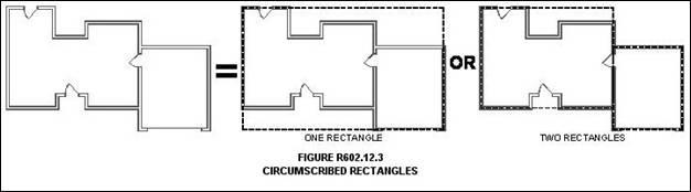
R602.12.3 Circumscribed rectangle. Required length of bracing shall be determined by circumscribing one or more rectangles around the entire building or portions thereof as shown in Figure R602.12.3. Rectangles shall surround all enclosed offsets and projections such as sunrooms and attached garages. Chimneys, partial height projections, and open structures, such as carports and decks, shall be excluded from the rectangle. Each rectangle shall have no side greater than 80 feet (24 384 (24,384 mm) with a maximum 3:1 ratio between the long and short side. Rectangles shall be permitted to be skewed to accommodate angled projections as shown in Figure R602.12.4.3.
R602.12.4 Required length of bracing. The required length of bracing for each side of a circumscribed rectangle shall be determined using Table R602.12.4. Where multiple rectangles share a common side or sides, the required length of bracing shall equal the sum of the required lengths from all shared rectangle sides.
Table R602.12.4
Required Length of Bracing Along Each Side of a Circumscribed Rectanglea,b,c |
Wind Speed | Eave-to-Ridge Height (feet) | Number of Floor Levels Abovee,f | Required Length of Bracing on Front/Rear Side (feet) | Required Length of Bracing on Left/Right Side (feet) |
Length of Left/Right Side (feet) | Length of Front/Rear Side (feet) |
10 | 20 | 30 | 40 | 50 | 60 | 70 | 80 | 10 | 20 | 30 | 40 | 50 | 60 | 70 | 80 |
115 | 10 | 0 | 2.0 | 3.5 | 5.0 | 6.0 | 7.5 | 9.0 | 10.5 | 12.0 | 2.0 | 3.5 | 5.0 | 6.0 | 7.5 | 9.0 | 10.5 | 12.0 |
1d | 3.5 | 6.5 | 9.0 | 12.0 | 14.5 | 17.0 | 19.8 | 22.6 | 3.5 | 6.5 | 9.0 | 12.0 | 14.5 | 17.0 | 19.8 | 22.6 |
2d | 5.0 | 9.5 | 13.5 | 17.5 | 21.5 | 25.0 | 29.2 | 33.4 | 5.0 | 9.5 | 13.5 | 17.5 | 21.5 | 25.0 | 29.2 | 33.4 |
15 | 0 | 2.6 | 4.6 | 6.5 | 7.8 | 9.8 | 11.7 | 13.7 | 15.7 | 2.6 | 4.6 | 6.5 | 7.8 | 9.8 | 11.7 | 13.7 | 15.7 |
1d | 4.0 | 7.5 | 10.4 | 13.8 | 16.7 | 19.6 | 22.9 | 26.2 | 4.0 | 7.5 | 10.4 | 13.8 | 16.7 | 19.6 | 22.9 | 26.2 |
2d | 5.5 | 10.5 | 14.9 | 19.3 | 23.7 | 27.5 | 32.1 | 36.7 | 5.5 | 10.5 | 14.9 | 19.3 | 23.7 | 27.5 | 32.1 | 36.7 |
20 | 0 | 2.9 | 5.2 | 7.3 | 8.8 | 11.1 | 13.2 | 15.4 | 17.6 | 2.9 | 5.2 | 7.3 | 8.8 | 11.1 | 13.2 | 15.4 | 17.6 |
1d | 4.5 | 8.5 | 11.8 | 15.6 | 18.9 | 22.1 | 25.8 | 29.5 | 4.5 | 8.5 | 11.8 | 15.6 | 18.9 | 22.1 | 25.8 | 29.5 |
2d | 6.2 | 11.9 | 16.8 | 21.8 | 27.3 | 31.1 | 36.3 | 41.5 | 6.2 | 11.9 | 16.8 | 21.8 | 27.3 | 31.1 | 36.3 | 41.5 |
130 | 10 | 0 | 2.5 | 4.0 | 6.0 | 7.5 | 9.5 | 11.0 | 12.8 | 14.6 | 2.5 | 4.0 | 6.0 | 7.5 | 9.5 | 11.0 | 12.8 | 14.6 |
1d | 4.5 | 8.0 | 11.0 | 14.5 | 18.0 | 21.0 | 24.5 | 28.0 | 4.5 | 8.0 | 11.0 | 14.5 | 18.0 | 21.0 | 24.5 | 28.0 |
2d | 6.0 | 11.5 | 16.5 | 21.5 | 26.5 | 31.0 | 36.2 | 41.4 | 6.0 | 11.5 | 16.5 | 21.5 | 26.5 | 31.0 | 36.2 | 41.4 |
15 | 0 | 3.4 | 5.2 | 7.8 | 9.8 | 12.4 | 14.3 | 16.7 | 19.1 | 3.4 | 5.2 | 7.8 | 9.8 | 12.4 | 14.3 | 16.7 | 19.1 |
1d | 5.2 | 9.2 | 12.7 | 16.7 | 20.7 | 24.2 | 28.2 | 32.2 | 5.2 | 9.2 | 12.7 | 16.7 | 20.7 | 24.2 | 28.2 | 32.2 |
2d | 6.6 | 12.7 | 18.2 | 23.7 | 29.2 | 34.1 | 39.8 | 45.5 | 6.6 | 12.7 | 18.2 | 23.7 | 29.2 | 34.1 | 39.8 | 45.5 |
20 | 0 | 3.8 | 5.9 | 8.8 | 11.1 | 14.0 | 16.2 | 18.9 | 21.6 | 3.8 | 5.9 | 8.8 | 11.1 | 14.0 | 16.2 | 18.9 | 21.6 |
1d | 5.9 | 10.4 | 14.4 | 18.9 | 23.4 | 27.3 | 31.8 | 36.3 | 5.9 | 10.4 | 14.4 | 18.9 | 23.4 | 27.3 | 31.8 | 36.3 |
2d | 7.5 | 14.4 | 20.6 | 26.8 | 33.0 | 38.5 | 44.9 | 51.3 | 7.5 | 14.4 | 20.6 | 26.8 | 33.0 | 38.5 | 44.9 | 51.3 |
For SI: 1 ft = 304.8 mm. a. Interpolation shall be permitted; extrapolation shall be prohibited. b. For Exposure Category C, multiply the required length of bracing by a factor of 1.20 for a one-story building, 1.30 for a two-story building, and 1.40 for a three-story building. c. For wall height adjustments multiply the required length of bracing by the following factors: 0.90 for 8 feet (2438 mm), 0.95 for 9 feet (2743 mm), 1.0 for 10 feet (3048 mm), 1.05 for 11 feet (3353 mm), and 1.10 for 12 feet (3658 mm). d. Where braced wall panels supporting stories above have been sheathed in wood structural panels with edge fasteners spaced at 4 inches (102 mm) on center, multiply the required length of bracing by 0.83. e. A floor level, habitable or otherwise, contained wholly within the roof rafters or trusses shall not be considered a floor level for purposes of determining the required length of bracing. f. A rectangle side with differing number of floor levels above shall use the greatest number when determining the required length of bracing. |
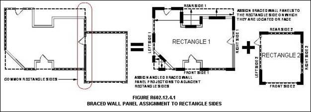
R602.12.4.1 Braced wall panel assignment to rectangle sides. Braced wall panels shall be assigned to the applicable rectangle side and contribute to its required length of bracing. Panels shall be assigned as specified below and as shown in Figure R602.12.4.1.
1. Exterior braced wall panels shall be assigned to the parallel rectangle side on which they are located or in which they face.
2. Interior braced wall panels shall be assigned to the parallel rectangle side on which they are located or in which they face up to 4 feet (1220 mm) away. Interior braced wall panels more than 4 feet (1220 mm) away from a parallel rectangle side shall not contribute.
3. The projections of angled braced wall panels shall be assigned to the adjacent rectangle sides.
R602.12.4.2 Contributing length. The cumulative contributing length of braced wall panels assigned to a rectangle side shall be greater than or equal to the required length of bracing as determined in Section R602.12.4. The contributing length of a braced wall panel shall be as specified below. When applying contributing length to angled braced wall panels, apply the requirements below to each projection:
1. Exterior braced wall panels shall contribute their actual length.
2. Interior braced wall panels shall contribute one-half of their actual length.
3. The contributing length of Methods ABW, PFH, PFG, and CS-PF shall be in accordance with Table R602.10.5.
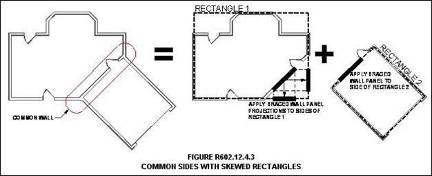
R602.12.4.3 Common sides with skewed rectangles. Braced wall panels located on a common wall where skewed rectangles intersect, as shown in Figure R602.12.4.3, shall be permitted to be assigned to the parallel rectangle side, and their projections shall be permitted to be assigned to the adjacent skewed rectangle sides.
R602.12.5 Cripple walls and framed walls of walk-out basements. For rectangle sides with cripple walls having a maximum height of 48 inches (1220 mm), the required length of bracing shall be as determined in Section R602.12.4. For rectangle sides with cripple walls having a height greater than 48 inches (1220 mm) at any location or framed walls of a walk-out basement, the required length of bracing shall be determined using Table R602.12.4. Braced wall panels within cripple walls and walls of walk-out basements shall comply with Item 4 of Section R602.12.2.
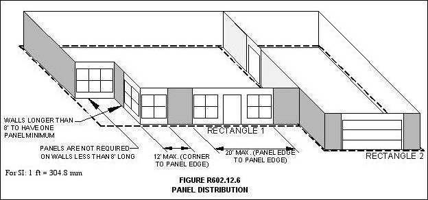
R602.12.6 Distribution of braced wall panels. Braced wall panels shall be distributed in accordance with the following requirements as shown in Figure R602.12.6.
1. The edge of a braced wall panel shall be no more than 12 feet (3658 mm) from any building corner or rectangle corner.
2. The distance between adjacent edges of braced wall panels shall be no more than 20 feet (6096 mm).
3. Segments of exterior walls greater than 8 feet (2438 mm) in length shall have a minimum of one braced wall panel.
4. Segments of exterior wall 8 feet (2438 mm) or less in length shall be permitted to have no braced wall panels.
R602.12.4 Required length of bracing. The required length of bracing for each side of a circumscribed rectangle shall be determined using Table R602.12.4. Where multiple rectangles share a common side or sides, the required length of bracing shall equal the sum of the required lengths from all shared rectangle sides.
Table R602.12.4
Required Length of Bracing Along Each Side of a Circumscribed Rectanglea,b,c |
Wind Speed | Eave-to-Ridge Height (feet) | Number of Floor Levels Abovee,f | Required Length of Bracing on Front/Rear Side (feet) | Required Length of Bracing on Left/Right Side (feet) |
Length of Left/Right Side (feet) | Length of Front/Rear Side (feet) |
10 | 20 | 30 | 40 | 50 | 60 | 70 | 80 | 10 | 20 | 30 | 40 | 50 | 60 | 70 | 80 |
115 | 10 | 0 | 2.0 | 3.5 | 5.0 | 6.0 | 7.5 | 9.0 | 10.5 | 12.0 | 2.0 | 3.5 | 5.0 | 6.0 | 7.5 | 9.0 | 10.5 | 12.0 |
1d | 3.5 | 6.5 | 9.0 | 12.0 | 14.5 | 17.0 | 19.8 | 22.6 | 3.5 | 6.5 | 9.0 | 12.0 | 14.5 | 17.0 | 19.8 | 22.6 |
2d | 5.0 | 9.5 | 13.5 | 17.5 | 21.5 | 25.0 | 29.2 | 33.4 | 5.0 | 9.5 | 13.5 | 17.5 | 21.5 | 25.0 | 29.2 | 33.4 |
15 | 0 | 2.6 | 4.6 | 6.5 | 7.8 | 9.8 | 11.7 | 13.7 | 15.7 | 2.6 | 4.6 | 6.5 | 7.8 | 9.8 | 11.7 | 13.7 | 15.7 |
1d | 4.0 | 7.5 | 10.4 | 13.8 | 16.7 | 19.6 | 22.9 | 26.2 | 4.0 | 7.5 | 10.4 | 13.8 | 16.7 | 19.6 | 22.9 | 26.2 |
2d | 5.5 | 10.5 | 14.9 | 19.3 | 23.7 | 27.5 | 32.1 | 36.7 | 5.5 | 10.5 | 14.9 | 19.3 | 23.7 | 27.5 | 32.1 | 36.7 |
20 | 0 | 2.9 | 5.2 | 7.3 | 8.8 | 11.1 | 13.2 | 15.4 | 17.6 | 2.9 | 5.2 | 7.3 | 8.8 | 11.1 | 13.2 | 15.4 | 17.6 |
1d | 4.5 | 8.5 | 11.8 | 15.6 | 18.9 | 22.1 | 25.8 | 29.5 | 4.5 | 8.5 | 11.8 | 15.6 | 18.9 | 22.1 | 25.8 | 29.5 |
2d | 6.2 | 11.9 | 16.8 | 21.8 | 27.3 | 31.1 | 36.3 | 41.5 | 6.2 | 11.9 | 16.8 | 21.8 | 27.3 | 31.1 | 36.3 | 41.5 |
130 | 10 | 0 | 2.5 | 4.0 | 6.0 | 7.5 | 9.5 | 11.0 | 12.8 | 14.6 | 2.5 | 4.0 | 6.0 | 7.5 | 9.5 | 11.0 | 12.8 | 14.6 |
1d | 4.5 | 8.0 | 11.0 | 14.5 | 18.0 | 21.0 | 24.5 | 28.0 | 4.5 | 8.0 | 11.0 | 14.5 | 18.0 | 21.0 | 24.5 | 28.0 |
2d | 6.0 | 11.5 | 16.5 | 21.5 | 26.5 | 31.0 | 36.2 | 41.4 | 6.0 | 11.5 | 16.5 | 21.5 | 26.5 | 31.0 | 36.2 | 41.4 |
15 | 0 | 3.4 | 5.2 | 7.8 | 9.8 | 12.4 | 14.3 | 16.7 | 19.1 | 3.4 | 5.2 | 7.8 | 9.8 | 12.4 | 14.3 | 16.7 | 19.1 |
1d | 5.2 | 9.2 | 12.7 | 16.7 | 20.7 | 24.2 | 28.2 | 32.2 | 5.2 | 9.2 | 12.7 | 16.7 | 20.7 | 24.2 | 28.2 | 32.2 |
2d | 6.6 | 12.7 | 18.2 | 23.7 | 29.2 | 34.1 | 39.8 | 45.5 | 6.6 | 12.7 | 18.2 | 23.7 | 29.2 | 34.1 | 39.8 | 45.5 |
20 | 0 | 3.8 | 5.9 | 8.8 | 11.1 | 14.0 | 16.2 | 18.9 | 21.6 | 3.8 | 5.9 | 8.8 | 11.1 | 14.0 | 16.2 | 18.9 | 21.6 |
1d | 5.9 | 10.4 | 14.4 | 18.9 | 23.4 | 27.3 | 31.8 | 36.3 | 5.9 | 10.4 | 14.4 | 18.9 | 23.4 | 27.3 | 31.8 | 36.3 |
2d | 7.5 | 14.4 | 20.6 | 26.8 | 33.0 | 38.5 | 44.9 | 51.3 | 7.5 | 14.4 | 20.6 | 26.8 | 33.0 | 38.5 | 44.9 | 51.3 |
For SI: 1 ft = 304.8 mm. a. Interpolation shall be permitted; extrapolation shall be prohibited. b. For Exposure Category C, multiply the required length of bracing by a factor of 1.20 for a one-story building, 1.30 for a two-story building, and 1.40 for a three-story building. c. For wall height adjustments multiply the required length of bracing by the following factors: 0.90 for 8 feet (2438 mm), 0.95 for 9 feet (2743 mm), 1.0 for 10 feet (3048 mm), 1.05 for 11 feet (3353 mm), and 1.10 for 12 feet (3658 mm). d. Where braced wall panels supporting stories above have been sheathed in wood structural panels with edge fasteners spaced at 4 inches (102 mm) on center, multiply the required length of bracing by 0.83. e. A floor level, habitable or otherwise, contained wholly within the roof rafters or trusses shall not be considered a floor level for purposes of determining the required length of bracing. f. A rectangle side with differing number of floor levels above shall use the greatest number when determining the required length of bracing. |
R602.12.4.1 Braced wall panel assignment to rectangle sides. Braced wall panels shall be assigned to the applicable rectangle side and contribute to its required length of bracing. Panels shall be assigned as specified below and as shown in Figure R602.12.4.1.
1. Exterior braced wall panels shall be assigned to the parallel rectangle side on which they are located or in which they face.
2. Interior braced wall panels shall be assigned to the parallel rectangle side on which they are located or in which they face up to 4 feet (1220 mm) away. Interior braced wall panels more than 4 feet (1220 mm) away from a parallel rectangle side shall not contribute.
3. The projections of angled braced wall panels shall be assigned to the adjacent rectangle sides.
R602.12.4.2 Contributing length. The cumulative contributing length of braced wall panels assigned to a rectangle side shall be greater than or equal to the required length of bracing as determined in Section R602.12.4. The contributing length of a braced wall panel shall be as specified below. When applying contributing length to angled braced wall panels, apply the requirements below to each projection:
1. Exterior braced wall panels shall contribute their actual length.
2. Interior braced wall panels shall contribute one-half of their actual length.
3. The contributing length of Methods ABW, PFH, PFG, and CS-PF shall be in accordance with Table R602.10.5.
R602.12.4.3 Common sides with skewed rectangles. Braced wall panels located on a common wall where skewed rectangles intersect, as shown in Figure R602.12.4.3, shall be permitted to be assigned to the parallel rectangle side, and their projections shall be permitted to be assigned to the adjacent skewed rectangle sides.
R602.12.5 Cripple walls and framed walls of walk-out basements. For rectangle sides with cripple walls having a maximum height of 48 inches (1220 mm), the required length of bracing shall be as determined in Section R602.12.4. For rectangle sides with cripple walls having a height greater than 48 inches (1220 mm) at any location or framed walls of a walk-out basement, the required length of bracing shall be determined using Table R602.12.4. Braced wall panels within cripple walls and walls of walk-out basements shall comply with Item 4 of Section R602.12.2.
R602.12.6 Distribution of braced wall panels. Braced wall panels shall be distributed in accordance with the following requirements as shown in Figure R602.12.6.
1. The edge of a braced wall panel shall be no more than 12 feet (3658 mm) from any building corner or rectangle corner.
2. The distance between adjacent edges of braced wall panels shall be no more than 20 feet (6096 mm).
3. Segments of exterior walls greater than 8 feet (2438 mm) in length shall have a minimum of one braced wall panel.
4. Segments of exterior wall 8 feet (2438 mm) or less in length shall be permitted to have no braced wall panels.
R602.12.6.1 Panels adjacent to balloon framed walls. Braced wall panels shall be placed on each side of each story adjacent to balloon framed walls designed in accordance with Section R602.3 with a maximum height of two stories.
R602.12.7 Braced wall panel connection. Braced wall panels shall be connected to other structural elements in accordance with Section R602.10.8.
R602.12.8 Braced wall panel support. Braced wall panels shall be supported in accordance with Section R602.10.9.
54. Change Sections R802.2 and R802.3 to read:
R802.2 Design and construction. The roof and ceiling assembly shall provide continuous ties across the structure to prevent roof thrust from being applied to the supporting walls. The assembly shall be designed and constructed in accordance with the provisions of this chapter and Figures R606.11(1), R606.11(2) and R606.11(3) or in accordance with AWC NDS.
R802.3 Ridge. A ridge board used to connect opposing rafters shall be not less than 1 inch (25 mm) nominal thickness and not less in depth than the cut end of the rafter. Where ceiling joist or rafter ties do not provide a continuous ties across the structure, a ridge beam shall be provided and supported on each end by a wall or girder.
55. Delete Sections R802.3.1, R802.3.2 and R802.3.3.
56. Change Section R802.4 and add Section R802.4.1 to read:
R802.4 Rafters. Rafters shall be in accordance with this section.
R802.4.1 Rafter size. Rafters shall be sized based on the rafter spans in Tables R802.4.1(1) through R802.4.1(8). Rafter spans shall be measured along the horizontal projection of the rafter. For other grades and species and for other loading conditions, refer to the AWC STJR.
57. Change the titles of Tables R802.4(1) and R802.4(2) to Tables R802.5.1(1) and R802.5.1(2), respectively, and change the titles of Tables R802.5.1(1) through R802.5.1(8) to Tables R802.4.1(1) through R802.4.1(8), respectively.
58. Add Sections R802.4.2 through R802.4.5 to read:
R802.4.2 Framing details. Rafters shall be framed not more than 1-1/2 inches (38 mm) offset from each other to a ridge board or directly opposite from each other with a collar tie, gusset plate or ridge strap in accordance with Table R602.3(1). Rafters shall be nailed to the top wall plates in accordance with Table R602.3(1) unless the roof assembly is required to comply with the uplift requirements of Section R802.11.
R802.4.3 Hips and valleys. Hip and valley rafters shall be not less than 2 inches (51 mm) nominal in thickness and not less in depth than the cut end of the rafter. Hip and valley rafters shall be supported at the ridge by a brace to a bearing partition or be designed to carry and distribute the specific load at that point.
R802.4.4 Rafter supports. Where the roof pitch is less than 3:12 (25% slope), structural members that support rafters, such as ridges, hips and valleys, shall be designed as beams, and bearing shall be provided for rafters in accordance with Section R802.6.
R802.4.5 Purlins. Installation of purlins to reduce the span of rafters is permitted as shown in Figure R802.4.5. Purlins shall be sized not less than the required size of the rafters that they support. Purlins shall be continuous and shall be supported by 2-inch by 4-inch (51 mm by 102 mm) braces installed to bearing walls at a slope not less than 45 degrees (0.79 rad) from the horizontal. The braces shall be spaced not more than 4 feet (1219 mm) on center and the unbraced length of braces shall not exceed 8 feet (2438 mm).
59. Add Figure R802.4.5 to read:
EDITOR'S NOTE: Figure R802.4.5, Brace Rafter Construction, is deleted; therefore the figure is not set out.
60. Add Section R802.4.6 to read:
R802.4.6 Collar ties. Where collar ties are used to connect opposing rafters, they shall be located in the upper third of the attic space and fastened in accordance with Table R602.3(1). Collar ties shall be not less than 1 inch by 4 inches (25 mm by 102 mm) nominal, spaced not more than 4 feet (1219 mm) on center. Ridge straps in accordance with Table R602.3(1) shall be permitted to replace collar ties.
61. Change Sections R802.5 and R802.5.1 to read:
R802.5 Ceiling joists. Ceiling joists shall be continuous across the structure or securely joined where they meet over interior partitions in accordance with Table R802.5.2.
R802.5.1 Ceiling joist size. Ceiling joists shall be sized based on the joist spans in Tables R802.4(1) and R802.4(2). For other grades and species and for other loading conditions, refer to the AWC STJR.
62. Delete Figure R802.5.1 and change the title of Table R802.5.1(9) to Table R802.5.2.
63. Add Section R802.5.2 to read:
R802.5.2 Ceiling joist and rafter connections. Where ceiling joists run parallel to rafters, they shall be connected to rafters at the top wall plate in accordance with Table R802.5.2. Where ceiling joists are not connected to the rafters at the top wall plate, they shall be installed in the bottom third of the rafter height in accordance with Figure R802.4.5 and Table R802.5.2. Where the ceiling joists are installed above the bottom third of the rafter height, the ridge shall be designed as a beam. Where ceiling joists do not run parallel to rafters, the ceiling joists shall be connected to top plates in accordance with Table R602.3(1). Each rafter shall be tied across the structure with a rafter tie or a 2-inch by 4-inch (51 mm x 102 mm) kicker connected to the ceiling diaphragm with nails equivalent in capacity to Table R802.5.2.
64. Add Sections R802.5.2.1 through R802.5.2.3 to read:
R802.5.2.1 Ceiling joists lapped. Ends of ceiling joists shall be lapped a minimum of 3 inches (76 mm) or butted over bearing partitions or beams and toenailed to the bearing member. Where ceiling joists are used to provide resistance to rafter thrust, lapped joists shall be nailed together in accordance with Table R802.5.2, and butted joists shall be tied together in a manner to resist such thrust. Joists that do not resist thrust shall be permitted to be nailed in accordance with Table R602.3(1). Wood structural panel roof sheathing, in accordance with Table R503.2.1.1(1), shall not cantilever more than 9 inches (229 mm) beyond the gable endwall unless supported by gable overhang framing.
R802.5.2.2 Rafter ties. Wood rafter ties shall be not less than 2 inches by 4 inches (51 mm by 102 mm) installed in accordance with Table R802.5.2 at each rafter. Other approved rafter tie methods shall be permitted.
R802.5.2.3 Blocking. Blocking shall be not less than utility grade lumber.
65. 57. Delete Section R905.2.8.5.
66. 58. Change Section R1001.8 to read:
R1001.8 Smoke chamber. Smoke chamber walls shall be constructed of solid masonry units, hollow masonry units grouted solid, stone, or concrete. The total minimum thickness of front, back, and side walls shall be 8 inches (203 mm) of solid masonry. When the inside surface of the smoke chamber is formed by corbelled masonry, the inside surface shall be parged smooth. When a lining of firebrick at least 2 inches (51 mm) thick, or a lining of vitrified clay at least 5/8 inch (16 mm) thick, is provided, the total minimum thickness of front, back, and side walls shall be 6 inches (152 mm) of solid masonry, including the lining. Firebrick shall conform to ASTM C 1261 and shall be laid with medium duty refractory mortar conforming to ASTM C 199. Vitrified clay linings shall conform to ASTM C 315.
67. 59. Change Section N1101.13 (R401.2) to read:
N1101.13 (R401.2) Compliance. Projects shall comply with all provisions of Chapter 11 labeled "Mandatory" and one of the following:
1. Sections N1101.14 through N1104.
2. Section N1105.
3. Section N1106.
4. The most recent version of REScheck, keyed to the 2015 2018 IECC.
Note: See REScheck compliance guidance issued by DHCD, available at the Department's website.
68. Delete 60. Change Section N1101.14 (R401.3). to read:
N1101.14 (R401.3) Certificate mandatory. A permanent certificate shall be completed by the builder or other approved party and posted on a wall in the space where the furnace is located, a utility room or an approved location inside the building. Where located on an electrical panel, the certificate shall not cover or obstruct the visibility of the circuit directory label, service disconnect label, or other required labels. The certificate shall indicate the predominant R-values of insulation installed in or on ceilings, roofs, walls, or foundation components, such as slabs, basement walls, crawl space walls, and floors and ducts outside conditioned spaces; U-factors of fenestration and the solar heat gain coefficient (SHGC) of fenestration; and the results from any required duct system and building envelope air leakage testing performed on the building. Where there is more than one value for each component, the certificate shall indicate the value covering the largest area. The certificate shall indicate the types and efficiencies of heating, cooling, and service water heating equipment. Where a gas-fired unvented room heater, electric furnace, or baseboard electric heater is installed in the residence, the certificate shall indicate "gas-fired unvented room heater," "electric furnace," or "baseboard electric heater," as appropriate. An efficiency shall not be indicated for gasfired unvented room heaters, electric furnaces, and electric baseboard heaters.
69. 61. Change the ceiling R-value and wood frame wall R-value categories for climate zone "4 except Marine" in Table N1102.1.2 (R402.1.2) to read:
Ceiling R-Value | Wood Frame Wall R-Value |
38 | 15 or 13 + 1h |
70. 62. Change the ceiling U-factor and frame wall U-factor categories for climate zone "4 except Marine" in Table N1102.1.4 (R402.1.4) to read:
Ceiling U-Factor | Frame Wall U-Factor |
0.030 | 0.079 |
71. 63. Change Section N1102.2.4 (R402.2.4) to read:
N1102.2.4 (R402.2.4) Access hatches and doors. Access doors from conditioned spaces to unconditioned spaces (e.g., attics and crawl spaces) shall be weatherstripped and insulated in accordance with the following values:
1. Hinged vertical doors shall have a minimum overall R-5 insulation value;
2. Hatches and scuttle hole covers shall be insulated to a level equivalent to the insulation on the surrounding surfaces; and
3. Pull down stairs shall have a minimum of 75% of the panel area having R-5 rigid insulation.
Access shall be provided to all equipment that prevents damaging or compressing the insulation. A wood framed or equivalent baffle or retainer is required to be provided when loose fill insulation is installed, the purpose of which is to prevent the loose fill insulation from spilling into the living space when the attic access is opened, and to provide a permanent means of maintaining the installed R-value of the loose fill insulation.
72. 64. Change Sections N1102.4 (R402.4) and N1102.4.1.1 (R402.4.1.1) to read:
N1102.4 (R402.4) Air leakage. The building thermal envelope shall be constructed to limit air leakage in accordance with the requirements of Sections N1102.4.1 through N1102.4.4.
N1102.4.1.1 (R402.4.1.1) Installation (Mandatory). The components of the building thermal envelope as listed in Table N1102.4.1.1 shall be installed in accordance with the manufacturer's instructions and the criteria listed in Table N1102.4.1.1, as applicable to the method of construction. Where required by the code official, an approved third party shall inspect all components and verify compliance.
73. 65. Change the title of the "Insulation Installation Criteria" category of Table N1102.4.1.1 (R402.4.1.1); change the "Shower/tub on exterior wall" category of Table N1102.4.1.1 (R402.4.1.1), and add footnotes "b" and "c" to Table N1102.4.1.1 (R402.4.1.1) to read:
Component | Air Barrier Criteria | Insulation Installation Criteriab |
Shower/tub on exterior wallc | The air barrier installed at exterior walls adjacent to showers and tubs shall be installed on the interior side and separate the exterior walls from the showers and tubs. | Exterior walls adjacent to showers and tubs shall be insulated. |
b. Structural integrity of headers shall be in accordance with the applicable building code. c. Air barriers used behind showers and tubs on exterior walls shall be of a permeable material that does not cause the entrapment of moisture in the stud cavity. |
74. 66. Change Section N1102.4.1.2 (R402.4.1.2) and add Sections N1102.4.1.2.1 (R402.4.1.2.1), N1102.4.1.2.2 (R402.4.1.2.2), and N1102.4.1.3 (R402.4.1.3) to read:
N1102.4.1.2 (R402.4.1.2) Air sealing. Building envelope air tightness shall be demonstrated to comply with either Section N1102.4.1.2.1 or N1102.4.1.2.2.
N1102.4.1.2.1 (R402.4.1.2.1) Testing option. The building or dwelling unit shall be tested for and verified as having an air leakage rate not exceeding five air changes per hour in Climate Zone 4. Testing shall be conducted in accordance with a blower door RESNET/ICC 380, ASTM E 779, or ASTM E 1827 and reported at a pressure of 0.2 inches w.g. (50 Pa). Where required by the building official, testing shall be conducted by an approved third party. A written report of the results of the test shall be signed by the party conducting the test and provided to the building official. Testing shall be conducted by a Virginia licensed general contractor, a Virginia licensed HVAC contractor, a Virginia licensed home inspector, a Virginia registered design professional, a certified BPI Envelope Professional, a certified HERS rater, or a certified duct and envelope tightness rater. The party conducting the test shall have been trained on the equipment used to perform the test. Testing shall be performed at any time after creation of all penetrations of the building thermal envelope.
Note: Should additional sealing be required as a result of the test, consideration may be given to the issuance of temporary certificate of occupancy in accordance with Section 116.1.1.
During testing:
1. Exterior windows and doors and fireplace and stove doors shall be closed, but not sealed beyond the intended weatherstripping or other infiltration control measures;
2. Dampers, including exhaust, intake, makeup air, backdraft, and flue dampers shall be closed, but not sealed beyond intended infiltration control measures;
3. Interior doors, if installed at the time of the test, shall be open;
4. Exterior doors for continuous ventilation systems and heat recovery ventilators shall be closed and sealed;
5. Heating and cooling systems, if installed at the time of the test, shall be turned off; and
6. Supply and return registers, if installed at the time of the test, shall be fully open.
N1102.4.1.2.2 (R402.4.1.2.2) Visual inspection option. Building envelope tightness shall be considered acceptable when the items listed in Table N1102.4.1.1, applicable to the method of construction, are field verified. Where required by the building official, an approved party, independent from the installer, shall inspect the air barrier. When this option is chosen, whole-house mechanical ventilation shall be provided in accordance with Section M1507.3.
N1102.4.1.3 (R402.4.1.3) Leakage rate (Prescriptive). The building or dwelling unit shall have an air leakage rate less than 5 changes per hour as verified in accordance with Section N1102.4.1.2.
75. 67. Change Section N1103.3.3 (R403.3.3) to read:
N1103.3.3 (R403.3.3) Duct testing (Mandatory). Ducts shall be pressure tested to determine air leakage by one of the following methods:
1. Rough-in test: Total leakage shall be measured with a pressure differential of 0.1 inch w.g. (25 Pa) across the system, including the manufacturer's air handler enclosure if installed at the time of the test. All registers shall be taped or otherwise sealed during the test.
2. Postconstruction test: Total leakage shall be measured with a pressure differential of 0.1 inch w.g. (25 Pa) across the entire system, including the manufacturer's air handler enclosure. Registers shall be taped or otherwise sealed during the test.
Exception: A duct air leakage test shall not be required where the ducts and air handlers are located entirely within the building thermal envelope.
A written report of the results of the test shall be signed by the party conducting the test and provided to the code official. The licensed mechanical contractor installing the mechanical system shall be permitted to perform the duct testing. The contractor shall have been trained on the equipment used to perform the test.
68. Delete Section N1103.3.5 (R403.3.5).
76. 69. Change Section N1103.7 (R403.7) to read:
N1103.7 (R403.7) Equipment and appliance sizing. Heating and cooling equipment and appliances shall be sized in accordance with ACCA Manual S or other approved sizing methodologies based on building loads calculated in accordance with ACCA Manual J or other approved heating and cooling calculation methodologies.
Exception: Heating and cooling equipment and appliance sizing shall not be limited to the capacities determined in accordance with Manual S or other approved sizing methodologies where any of the following conditions apply:
1. The specified equipment or appliance utilizes multi-stage technology or variable refrigerant flow technology and the loads calculated in accordance with the approved heating and cooling methodology fall within the range of the manufacturer's published capacities for that equipment or appliance.
2. The specified equipment or appliance manufacturer's published capacities cannot satisfy both the total and sensible heat gains calculated in accordance with the approved heating and cooling methodology and the next larger standard size unit is specified.
3. The specified equipment or appliance is the lowest capacity unit available from the specified manufacturer.
77. 70. Change footnote for Table N1106.4 (R406.4) to read:
Table N1106.4 (R406.4)
Maximum Energy Rating Indexa
|
Climate Zone
| Energy Rating Index
|
1
| 52
|
2
| 52
|
3
| 51
|
4
| 62
|
5
| 55
|
6
| 54
|
7
| 53
|
8
| 53
|
a. When onsite renewable energy is included for compliance using the ERI analysis per Section N1106.4 (R406.4), the building shall meet the mandatory requirements of Section N1106.2 (R406.2) and the building thermal envelope shall be greater than or equal to levels of energy efficiency and solar heat gain coefficient in Table N1102.1.2 (R402.1.2), with a ceiling R-value of 49 and a wood frame wall R-value of 20 or 13+5, or Table N1102.1.4 (R402.1.4), with a ceiling U-factor of 0.026 and a frame wall U-factor of 0.060. |
78. 71. Delete Section N1109.1.1.1 (R503.1.1.1).
79. 72. Change Section M1401.3 to read:
M1401.3 Equipment and appliance sizing. Heating and cooling equipment and appliances shall be sized in accordance with ACCA Manual S or other approved sizing methodologies based on building loads calculated in accordance with ACCA Manual J or other approved heating and cooling calculation methodologies.
Exception: Heating and cooling equipment and appliance sizing shall not be limited to the capacities determined in accordance with Manual S or other approved sizing methodologies where any of the following conditions apply:
1. The specified equipment or appliance utilizes multi-stage technology or variable refrigerant flow technology and the loads calculated in accordance with the approved heating and cooling methodology fall within the range of the manufacturer's published capacities for that equipment or appliance.
2. The specified equipment or appliance manufacturer's published capacities cannot satisfy both the total and sensible heat gains calculated in accordance with the approved heating and cooling methodology, and the next larger standard size unit is specified.
3. The specified equipment or appliance is the lowest capacity unit available from the specified manufacturer.
80. 73. Add Section M1501.2 to read:
M1501.2 Transfer air. Air transferred from occupiable spaces other than kitchens, baths, and toilet rooms shall not be prohibited from serving as makeup air for exhaust systems. Transfer openings between spaces shall be of the same cross-sectional area as the free area of the makeup air openings. Where louvers and grilles are installed, the required size of openings shall be based on the net free area of each opening. Where the design and free area of louvers and grilles are not known, it shall be assumed that wood louvers will have 25% free area and metal louvers and grilles will have 75% free area.
81. 74. Change Section M1502.4.2 to read:
M1502.4.2 Duct installation. Exhaust ducts shall be supported at 4-foot (1219 mm) intervals and shall be secured in place. The insert end of the duct shall extend into the adjoining duct or fitting in the direction of airflow. Ducts shall not be joined with screws or similar fasteners that protrude into the inside of the duct. Where dryer exhaust ducts are enclosed in wall or ceiling cavities, such cavities shall allow the installation of the duct without deformation.
82. 75. Change Section M1503.4 M1503.6 to read:
M1503.4 M1503.6 Makeup air required. Exhaust hood systems capable of exhausting more than 400 cubic feet per minute (0.19 m3/s) shall be provided with makeup air at a rate approximately equal to the exhaust air rate in excess of 400 cubic feet per minute (0.19 m3/s). Such makeup air systems shall be equipped with a means of closure and shall be automatically controlled to start and operate simultaneously with the exhaust system.
Exception: Intentional openings for makeup air are not required for kitchen exhaust systems capable of exhausting not greater than 600 cubic feet per minute (0.28 m3/s) provided that one of the following conditions is met:
1. Where the floor area within the air barrier of a dwelling unit is at least 1500 1,500 square feet (139.35 m2), and where natural draft or mechanical draft space-heating or water-heating appliances are not located within the air barrier.
2. Where the floor area within the air barrier of a dwelling unit is at least 3000 3,000 square feet (278.71 m2), and where natural draft space-heating or water-heating appliances are not located within the air barrier.
83. 76. Add Section M1801.1.1 to read:
M1801.1.1 Equipment changes. Upon the replacement or new installation of any fuel-burning appliances or equipment in existing buildings, an inspection or inspections shall be conducted to ensure that the connected vent or chimney systems comply with the following:
1. Vent or chimney systems are sized in accordance with this code.
2. Vent or chimney systems are clean, free of any obstruction or blockages, defects or deterioration and are in operable condition.
Where not inspected by the local building department, persons performing such changes or installations shall certify to the building official that the requirements of Items 1 and 2 of this section are met.
84. 77. Change Sections G2411.1 and G2411.1.1 G2411.2 to read:
G2411.1 Pipe and tubing. Each above-group portion of a gas piping system that is likely to become energized shall be electrically continuous and bonded to an effective ground-fault current path. Gas piping shall be considered to be bonded where it is connected to appliances that are connected to the equipment grounding conductor of the circuit supplying that appliance. Corrugated stainless steel tubing (CSST) piping systems listed with an arc resistant jacket or coating system in accordance with ANSI LC 1/CSA 6.26 shall comply with this section. Where any CSST segments of a piping system are not listed with an arc resistant jacket or coating system in accordance with ANSI LC 1/CSA 6.26, Section G2411.1.1 G2411.2 shall apply.
G2411.1.1 G2411.2 CSST without arc resistant jacket or coating system. CSST gas piping systems and piping systems containing one or more segments of CSST not listed with an arc resistant jacket or coating system in accordance with ANSI LC 1/CSA 6.26 shall be bonded to the electrical service grounding electrode system or, where provided, the lightning protection electrode system and shall comply with Sections G2411.1.1.1 G2411.2.1 through G2411.1.1.5 G2411.2.5.
85. 78. Add Section G2425.1.1 to read:
G2425.1.1 Equipment changes. Upon the replacement or new installation of any fuel-burning appliances or equipment in existing buildings, an inspection or inspections shall be conducted to ensure that the connected vent or chimney systems comply with the following:
1. Vent or chimney systems are sized in accordance with this code.
2. Vent or chimney systems are clean, free of any obstruction or blockages, defects, or deterioration and are in operable condition.
Where not inspected by the local building department, persons performing such changes or installations shall certify to the building official that the requirements of Items 1 and 2 of this section are met.
86. 79. Change Section G2439.7.2 to read:
G2439.7.2 Duct installation. Exhaust ducts shall be supported at 4-foot (1219 mm) intervals and secured in place. The insert end of the duct shall extend into the adjoining duct or fitting in the direction of airflow. Ducts shall not be joined with screws or similar fasteners that protrude into the inside of the duct. Where dryer exhaust ducts are enclosed in wall or ceiling cavities, such cavities shall allow the installation of the duct without deformation.
87. 80. Change Section P2601.2 to read:
P2601.2 Connections. Plumbing fixtures, drains and appliances used to receive or discharge liquid wastes or sewage shall be directly connected to the sanitary drainage system of the building or premises, in accordance with the requirements of this code. This section shall not be construed to prevent indirect waste systems.
Exception: Bathtubs, showers, lavatories, clothes washers and laundry trays shall not be required to discharge to the sanitary drainage system where such fixtures discharge to an approved nonpotable gray water system in accordance with the applicable provisions of Sections P2910, P2911, and P2912.
88. 81. Change Section P2602.1 to read:
P2602.1 General. The water and drainage system of any building or premises where plumbing fixtures are installed shall be connected to a public or private water supply and a public or private sewer system. As provided for in Section 103.5 of Part I of the Virginia Uniform Statewide Building Code (13VAC5-63) for functional design, water supply sources and sewage disposal systems are regulated and approved by the Virginia Department of Health and the Virginia Department of Environmental Quality.
Note: See also the Memorandums of Agreement in the "Related Laws Package," which is available from the Virginia Department of Housing and Community Development.
89. 82. Add Section P2602.3 to read:
P2602.3 Tracer wire. Nonmetallic water service piping that connects to public systems shall be locatable. An insulated copper tracer wire, 18 AWG minimum in size and suitable for direct burial or an equivalent product, shall be utilized. The wire shall be installed in the same trench as the water service piping and within 12 inches (305 mm) of the pipe and shall be installed to within five feet (1524 mm) of the building wall to the point where the building water service pipe intersects with the public water supply. At a minimum, one end of the wire shall terminate above grade to provide access to the wire in a location that is resistant to physical damage, such as with a meter vault or at the building wall.
90. 83. Add Section P2901.1.1 to read:
P2901.1.1 Nonpotable fixtures and outlets. Nonpotable water shall be permitted to serve nonpotable type fixtures and outlets in accordance with the applicable provisions of Sections P2910, P2911, and P2912.
91. 84. Change Section P2903.5 to read:
P2903.5 Water hammer. The flow velocity of the water distribution system shall be controlled to reduce the possibility of water hammer. A water-hammer arrestor shall be installed where quick-closing valves are utilized, unless otherwise approved. Water hammer arrestors shall be installed in accordance with manufacturer's specifications. Water hammer arrestors shall conform to ASSE 1010.
85. Change Section P2906.2.1 to read:
P2906.2.1 Lead content of drinking water pipe and fittings. Pipe, pipe fittings, joints, valves, faucets, and fixture fittings utilized to supply water for drinking or cooking purposes shall comply with NSF 372.
92. 86. Change Sections P2910.1 through P2910.14, including subsections, to read:
P2910.1 Scope. The provisions of this section shall govern the materials, design, construction, and installation of nonpotable water systems subject to this code.
P2910.1.1 Design of nonpotable water systems. All portions of nonpotable water systems subject to this code shall be constructed using the same standards and requirements for the potable water systems or drainage systems as provided for in this code unless otherwise specified in this section or Section P2911 or P2912, as applicable.
P2910.2 Makeup water. Makeup water shall be provided for all nonpotable water supply systems. The makeup water system shall be designed and installed to provide supply of water in the amounts and at the pressures specified in this code. The makeup water supply shall be potable and be protected against backflow in accordance with the applicable requirements of Section P2902.
P2910.2.1 Makeup water sources. Nonpotable water shall be permitted to serve as makeup water for gray water and rainwater systems.
P2910.2.2 Makeup water supply valve. A full-open valve shall be provided on the makeup water supply line.
P2910.2.3 Control valve alarm. Makeup water systems shall be fitted with a warning mechanism that alerts the user to a failure of the inlet control valve to close correctly. The alarm shall activate before the water within the storage tank begins to discharge into the overflow system.
P2910.3 Sizing. Nonpotable water distribution systems shall be designed and sized for peak demand in accordance with approved engineering practice methods that comply with the applicable provisions of this chapter.
P2910.4 Signage required. All nonpotable water outlets, other than water closets and urinals, such as hose connections, open ended pipes, and faucets shall be identified at the point of use for each outlet with signage that reads as follows: "Nonpotable water is utilized for (insert application name). Caution: nonpotable water. DO NOT DRINK." The words shall be legibly and indelibly printed on a tag or sign constructed of corrosion-resistant waterproof material or shall be indelibly printed on the fixture. The letters of the words shall be not less than 0.5 inches (12.7 mm) in height and in colors in contrast to the background on which they are applied. The pictograph shown in Figure P2910.4 shall appear on the signage required by this section.

P2910.5 Potable water supply system connections. Where a potable water supply system is connected to a nonpotable water system, the potable water supply shall be protected against backflow in accordance with the applicable provisions of Section P2902.
P2910.6 Nonpotable water system connections. Where a nonpotable water system is connected and supplies water to another nonpotable water system, the nonpotable water system that supplies water shall be protected against backflow in accordance with the applicable provisions of Section P2902.
P2910.7 Approved components and materials. Piping, plumbing components, and materials used in the nonpotable water drainage and distribution systems shall be approved for the intended application and compatible with the water and any disinfection or treatment systems used.
P2910.8 Insect and vermin control. Nonpotable water systems shall be protected to prevent the entrance of insects and vermin into storage and piping systems. Screen materials shall be compatible with system material and shall not promote corrosion of system components.
P2910.9 Freeze protection. Nonpotable water systems shall be protected from freezing in accordance with the applicable provisions of Chapter 26.
P2910.10 Nonpotable water storage tanks. Nonpotable water storage tanks shall be approved for the intended application and comply with Sections P2910.10.1 through P2910.10.12.
P2910.10.1 Sizing. The holding capacity of storage tanks shall be sized for the intended use.
P2910.10.2 Inlets. Storage tank inlets shall be designed to introduce water into the tank and avoid agitating the contents of the storage tank. The water supply to storage tanks shall be controlled by fill valves or other automatic supply valves designed to stop the flow of incoming water before the tank contents reach the overflow pipes.
P2910.10.3 Outlets. Outlets shall be located at least 4 inches (102 mm) above the bottom of the storage tank and shall not skim water from the surface.
P2910.10.4 Materials and location. Storage tanks shall be constructed of material compatible with treatment systems used to treat water. Above grade storage vessels shall be constructed using opaque, UV-resistant materials such as tinted plastic, lined metal, concrete, or wood or painted to prevent algae growth. Above grade storage tanks shall be protected from direct sunlight unless their design specifically incorporates the use of the sunlight heat transfer. Wooden storage tanks shall be provided with a flexible liner. Storage tanks and their manholes shall not be located directly under soil or waste piping or sources of contamination.
P2910.10.5 Foundation and supports. Storage tanks shall be supported on a firm base capable of withstanding the storage tank's weight when filled to capacity. Storage tanks shall be supported in accordance with the applicable provisions of the IBC.
P2910.10.5.1 Ballast. Where the soil can become saturated, an underground storage tank shall be ballasted, or otherwise secured, to prevent the effects of buoyancy. The combined weight of the tank and hold down ballast shall meet or exceed the buoyancy force of the tank. Where the installation requires a foundation, the foundation shall be flat and shall be designed to support the storage tank weight when full, consistent with the bearing capability of adjacent soil.
P2910.10.5.2 Structural support. Where installed below grade, storage tank installations shall be designed to withstand earth and surface structural loads without damage.
P2910.10.6 Overflow. The storage tank shall be equipped with an overflow pipe having a diameter not less than that shown in Table P2910.10.6. The overflow outlet shall discharge at a point not less than 6 inches (152 mm) above the roof or roof drain, floor or floor drain, or over an open water-supplied fixture. The overflow outlet shall terminate through a check valve. Overflow pipes shall not be directed on walkways. The overflow drain shall not be equipped with a shutoff valve. A minimum of one cleanout shall be provided on each overflow pipe in accordance with the applicable provisions of Section P3005.2.
Table P2910.10.6
Sizes for Overflow Pipes for Water Supply Tanks |
Maximum Capacity of Water Supply Line to Tank (gpm) | Diameter of Overflow Pipe (inches) |
0 ‑ 50 | 2 |
50 ‑ 150 | 2-1/2 |
150 ‑ 200 | 3 |
200 ‑ 400 | 4 |
400 ‑ 700 | 5 |
700 ‑ 1,000 | 6 |
Over 1,000 | 8 |
For SI: 1 inch = 25.4 mm, 1 gallon per minute = 3.785 L/m. |
P2910.10.7 Access. A minimum of one access opening shall be provided to allow inspection and cleaning of the tank interior. Access openings shall have an approved locking device or other approved method of securing access. Below grade storage tanks, located outside of the building, shall be provided with either a manhole not less than 24 inches (610 mm) square or a manhole with an inside diameter not less than 24 inches (610 mm). The design and installation of access openings shall prohibit surface water from entering the tank. Each manhole cover shall have an approved locking device or other approved method of securing access.
Exception: Storage tanks under 800 gallons (3028 L) in volume installed below grade shall not be required to be equipped with a manhole, but shall have an access opening not less than 8 inches (203 mm) in diameter to allow inspection and cleaning of the tank interior.
P2910.10.8 Venting. Storage tanks shall be vented. Vents shall not be connected to the sanitary drainage system. Vents shall be at least equal in size to the internal diameter of the drainage inlet pipe or pipes connected to the tank. Where installed at grade, vents shall be protected from contamination by means of a U-bend installed with the opening directed downward. Vent outlets shall extend a minimum of 12 inches (304.8 mm) above grade, or as necessary to prevent surface water from entering the storage tank. Vent openings shall be protected against the entrance of vermin and insects. Vents serving gray water tanks shall terminate in accordance with the applicable provisions of Sections P3103 and P2910.8.
P2910.10.9 Drain. Where drains are provided, they shall be located at the lowest point of the storage tank. The tank drain pipe shall discharge as required for overflow pipes and shall not be smaller in size than specified in Table P2910.10.6. A minimum of one cleanout shall be provided on each drain pipe in accordance with Section P3005.2.
P2910.10.10 Labeling and signage. Each nonpotable water storage tank shall be labeled with its rated capacity and the location of the upstream bypass valve. Underground and otherwise concealed storage tanks shall be labeled at all access points. The label shall read: "CAUTION: NONPOTABLE WATER ‑ DO NOT DRINK." Where an opening is provided that could allow the entry of personnel, the opening shall be marked with the words: "DANGER ‑ CONFINED SPACE." Markings shall be indelibly printed on a tag or sign constructed of corrosion-resistant waterproof material mounted on the tank or shall be indelibly printed on the tank. The letters of the words shall be not less than 0.5 inches (12.7 mm) in height and shall be of a color in contrast with the background on which they are applied.
P2910.10.11 Storage tank tests. Storage tanks shall be tested in accordance with the following:
1. Storage tanks shall be filled with water to the overflow line prior to and during inspection. All seams and joints shall be left exposed and the tank shall remain water tight without leakage for a period of 24 hours.
2. After 24 hours, supplemental water shall be introduced for a period of 15 minutes to verify proper drainage of the overflow system and verify that there are no leaks.
3. Following a successful test of the overflow system, the water level in the tank shall be reduced to a level that is at 2 inches (50.8 mm) below the makeup water offset point. The tank drain shall be observed for proper operation. The makeup water system shall be observed for proper operation, and successful automatic shutoff of the system at the refill threshold shall be verified. Water shall not be drained from the overflow at any time during the refill test.
4. Air tests shall be permitted in lieu of water testing as recommended by the tank manufacturer or the tank standard.
P2910.10.12 Structural strength. Storage tanks shall meet the applicable structural strength requirements of the IBC.
P2910.11 Trenching requirements for nonpotable water system piping. Underground nonpotable water system piping shall be horizontally separated from the building sewer and potable water piping by 5 feet (1524 mm) of undisturbed or compacted earth. Nonpotable water system piping shall not be located in, under, or above sewage systems cesspools, septic tanks, septic tank drainage fields, or seepage pits. Buried nonpotable water system piping shall comply with the requirements of this code for the piping material installed.
Exceptions:
1. The required separation distance shall not apply where the bottom of the nonpotable water pipe within 5 feet (1524 mm) of the sewer is equal to or greater than 12 inches (305 mm) above the top of the highest point of the sewer and the pipe materials conforms to Table P3002.2.
2. The required separation distance shall not apply where the bottom of the potable water service pipe within 5 feet (1524 mm) of the nonpotable water pipe is a minimum of 12 inches (305 mm) above the top of the highest point of the nonpotable water pipe and the pipe materials comply with the requirements of Table P2906.5.
3. Nonpotable water pipe is permitted to be located in the same trench with building sewer piping, provided that such sewer piping is constructed of materials that comply with the requirements of Table P3002.1(2).
4. The required separation distance shall not apply where a nonpotable water pipe crosses a sewer pipe, provided that the pipe is sleeved to at least 5 feet (1524 mm) horizontally from the sewer pipe centerline on both sides of such crossing with pipe materials that comply with Table P3002.1(2).
5. The required separation distance shall not apply where a potable water service pipe crosses a nonpotable water pipe provided that the potable water service pipe is sleeved for a distance of at least 5 feet (1524 mm) horizontally from the centerline of the nonpotable pipe on both sides of such crossing with pipe materials that comply with Table P3002.1(2).
P2910.12 Outdoor outlet access. Sillcocks, hose bibs, wall hydrants, yard hydrants, and other outdoor outlets that are supplied by nonpotable water shall be located in a locked vault or shall be operable only by means of a removable key.
P2910.13 Drainage and vent piping and fittings. Nonpotable drainage and vent pipe and fittings shall comply with the applicable material standards and installation requirements in accordance with provisions of Chapter 30.
P2910.13.1 Labeling and marking. Identification of nonpotable drainage and vent piping shall not be required.
P2910.14 Pumping and control system. Mechanical equipment, including pumps, valves, and filters, shall be accessible and removable in order to perform repair, maintenance, and cleaning. The minimum flow rate and flow pressure delivered by the pumping system shall be designed for the intended application in accordance with the applicable provisions of Section P2903.
93. 87. Add Sections P2910.15 through P2910.18, including subsections, to read:
P2910.15 Water-pressure reducing valve or regulator. Where the water pressure supplied by the pumping system exceeds 80 psi (552 kPa) static, a pressure-reducing valve shall be installed to reduce the pressure in the nonpotable water distribution system piping to 80 psi (552 kPa) static or less. Pressure-reducing valves shall be specified and installed in accordance with the applicable provisions of Section P2903.3.1.
P2910.16 Distribution pipe. Distribution piping utilized in nonpotable water stems shall comply with Sections P2910.16.1 through P2910.16.4.
P2910.16.1 Materials, joints, and connections. Distribution piping and fittings shall comply with the applicable material standards and installation requirements in accordance with applicable provisions of Chapter 29.
P2910.16.2 Design. Distribution piping shall be designed and sized in accordance with the applicable provisions of Chapter 29.
P2910.16.3 Labeling and marking. Distribution piping labeling and marking shall comply with Section P2901.1 P2901.2.
P2910.16.4 Backflow prevention. Backflow preventers shall be installed in accordance with the applicable provisions of Section P2902.
P2910.17 Tests and inspections. Tests and inspections shall be performed in accordance with Sections P2910.17.1 through P2910.17.5.
P2910.17.1 Drainage and vent pipe test. Drain, waste, and vent piping used for gray water and rainwater nonpotable water systems shall be tested in accordance with the applicable provisions of Section P2503.
P2910.17.2 Storage tank test. Storage tanks shall be tested in accordance with the Section P2910.10.11.
P2910.17.3 Water supply system test. Nonpotable distribution piping shall be tested in accordance with Section P2503.7.
P2910.17.4 Inspection and testing of backflow prevention assemblies. The testing of backflow preventers and backwater valves shall be conducted in accordance with Section P2503.8.
P2910.17.5 Inspection of vermin and insect protection. Inlets and vent terminations shall be visually inspected to verify that each termination is installed in accordance with Section P2910.10.8.
P2910.18 Operation and maintenance manuals. Operations and maintenance materials for nonpotable water systems shall be provided as prescribed by the system component manufacturers and supplied to the owner to be kept in a readily accessible location.
94. 88. Change the title of Section P2911 to "Gray Water Nonpotable Water Systems."
95. 89. Change Sections P2911.1 through P2911.6, including subsections, to read:
P2911.1 Gray water nonpotable water systems. This code is applicable to the plumbing fixtures, piping or piping systems, storage tanks, drains, appurtenances, and appliances that are part of the distribution system for gray water within buildings and to storage tanks and associated piping that are part of the distribution system for gray water outside of buildings. This code does not regulate equipment used for, or the methods of, processing, filtering, or treating gray water, which may be regulated by the Virginia Department of Health or the Virginia Department of Environmental Quality.
P2911.1.1 Separate systems. Gray water nonpotable water systems, unless approved otherwise under the permit from the Virginia Department of Health, shall be separate from the potable water system of a building with no cross connections between the two systems except as permitted by the Virginia Department of Health.
P2911.2 Water quality. Each application of gray water reuse shall meet the minimum water quality requirements set forth in Sections P2911.2.1 through P2911.2.4 unless otherwise superseded by other state agencies.
P2911.2.1 Disinfection. Where the intended use or reuse application for nonpotable water requires disinfection or other treatment or both, it shall be disinfected as needed to ensure that the required water quality is delivered at the point of use or reuse.
P2911.2.2 Residual disinfectants. Where chlorine is used for disinfection, the nonpotable water shall contain not more than 4 parts per million (4 mg/L) of free chlorine, combined chlorine, or total chlorine. Where ozone is used for disinfection, the nonpotable water shall not exceed 0.1 parts per million (by volume) of ozone at the point of use.
P2911.2.3 Filtration. Water collected for reuse shall be filtered as required for the intended end use. Filters shall be accessible for inspection and maintenance. Filters shall utilize a pressure gauge or other approved method to indicate when a filter requires servicing or replacement. Shutoff valves installed immediately upstream and downstream of the filter shall be included to allow for isolation during maintenance.
P2911.2.4 Filtration required. Gray water utilized for water closet and urinal flushing applications shall be filtered by a 100 micron or finer filter.
P2911.3 Storage tanks. Storage tanks utilized in gray water nonpotable water systems shall comply with Section P2910.10.
P2911.4 Retention time limits. Untreated gray water shall be retained in storage tanks for a maximum of 24 hours.
P2911.5 Tank location. Storage tanks shall be located with a minimum horizontal distance between various elements as indicated in Table P2911.5.1.
Table P2911.5.1
Location of Nonpotable Gray Water Reuse Storage Tanks |
Element | Minimum Horizontal Distance from Storage Tank (feet) |
Lot line adjoining private lots | 5 |
Sewage systems | 5 |
Septic tanks | 5 |
Water wells | 50 |
Streams and lakes | 50 |
Water service | 5 |
Public water main | 10 |
P2911.6 Valves. Valves shall be supplied on gray water nonpotable water drainage systems in accordance with Sections P2911.6.1 and P2911.6.2.
P2911.6.1 Bypass valve. One three-way diverter valve certified to NSF 50 or other approved device shall be installed on collection piping upstream of each storage tank, or drainfield, as applicable, to divert untreated gray water to the sanitary sewer to allow servicing and inspection of the system. Bypass valves shall be installed downstream of fixture traps and vent connections. Bypass valves shall be labeled to indicate the direction of flow, connection, and storage tank or drainfield connection. Bypass valves shall be provided with access for operation and maintenance. Two shutoff valves shall not be installed to serve as a bypass valve.
P2911.6.2 Backwater valve. Backwater valves shall be installed on each overflow and tank drain pipe to prevent unwanted water from draining back into the storage tank. If the overflow and drain piping arrangement is installed to physically not allow water to drain back into the tank, such as in the form of an air gap, backwater valves shall not be required. Backwater valves shall be constructed and installed in accordance with Section P3008.
90. Delete Sections P2911.7 through P2911.13, including subsections.
96. 91. Change the title of Section P2912 to "Rainwater Nonpotable Water Systems."
97. 92. Change Sections P2912.1 through P2912.10, including subsections, to read:
P2912.1 General. The provisions of this section shall govern the design, construction, installation, alteration, and repair of rainwater nonpotable water systems for the collection, storage, treatment, and distribution of rainwater for nonpotable applications. The provisions of CSA B805/ICC 805 shall be permitted as an alternative to the provisions contained in this section for the design, construction, installation, alteration, and repair of rainwater nonpotable water systems for the collection, storage, treatment, and distribution of rainwater for nonpotable applications. Roof runoff or stormwater runoff collection surfaces shall be limited to roofing materials, public pedestrian accessible roofs, and subsurface collection identified in CSA B805/ICC 805 Table 7.1. Stormwater runoff shall not be collected from any other surfaces.
P2912.2 Water quality. Each application of rainwater reuse shall meet the minimum water quality requirements set forth in Sections P2912.2.1 through P2912.2.4 unless otherwise superseded by other state agencies.
P2912.2.1 Disinfection. Where the intended use or reuse application for nonpotable water requires disinfection or other treatment or both, it shall be disinfected as needed to ensure that the required water quality is delivered at the point of use or reuse.
P2912.2.2 Residual disinfectants. Where chlorine is used for disinfection, the nonpotable water shall contain not more than 4 parts per million (4 mg/L) of free chlorine, combined chlorine, or total chlorine. Where ozone is used for disinfection, the nonpotable water shall not exceed 0.1 parts per million (by volume) of ozone at the point of use.
P2912.2.3 Filtration. Water collected for reuse shall be filtered as required for the intended end use. Filters shall be accessible for inspection and maintenance. Filters shall utilize a pressure gauge or other approved method to indicate when a filter requires servicing or replacement. Shutoff valves installed immediately upstream and downstream of the filter shall be included to allow for isolation during maintenance.
P2912.2.4 Filtration required. Rainwater utilized for water closet and urinal flushing applications shall be filtered by a 100 micron or finer filter.
P2912.3 Collection surface. Rainwater shall be collected only from aboveground impervious roofing surfaces constructed from approved materials. Overflow or discharge piping from appliances or equipment or both, including but not limited to evaporative coolers, water heaters, and solar water heaters shall not discharge onto rainwater collection surfaces.
P2912.4 Collection surface diversion. At a minimum, the first 0.04 inches (1.016 mm) of each rain event of 25 gallons (94.6 L) per 1000 1,000 square feet (92.9 m2) shall be diverted from the storage tank by automatic means and not require the operation of manually operated valves or devices. Diverted water shall not drain onto other collection surfaces that are discharging to the rainwater system or to the sanitary sewer. Such water shall be diverted from the storage tank and discharged in an approved location.
P2912.5 Pre-tank filtration. Downspouts, conductors, and leaders shall be connected to a pre-tank filtration device. The filtration device shall not permit materials larger than 0.015 inches (0.4 mm).
P2912.6 Roof gutters and downspouts. Gutters and downspouts shall be constructed of materials that are compatible with the collection surface and the rainwater quality for the desired end use. Joints shall be made watertight.
P2912.6.1 Slope. Roof gutters, leaders, and rainwater collection piping shall slope continuously toward collection inlets. Gutters and downspouts shall have a slope of not less than 1 unit in 96 units along their entire length, and shall not permit the collection or pooling of water at any point.
P2912.6.2 Size. Gutters and downspouts shall be installed and sized in accordance with local rainfall rates.
P2912.6.3 Cleanouts. Cleanouts or other approved openings shall be provided to permit access to all filters, flushes, pipes, and downspouts.
P2912.7 Storage tanks. Storage tanks utilized in rainwater nonpotable water systems shall comply with Section P2910.10.
P2912.8 Location. Storage tanks shall be located with a minimum horizontal distance between various elements as indicated in Table P2912.8.1.
Table P2912.8.1
Location of Rainwater Storage Tanks |
Element | Minimum Horizontal Distance from Storage Tank (feet) |
Lot line adjoining private lots | 5 |
Sewage systems | 5 |
Septic tanks | 5 |
P2912.9 Valves. Valves shall be installed in collection and conveyance drainage piping of rainwater nonpotable water systems in accordance with Sections P2912.9.1 and P2912.9.2.
P2912.9.1 Influent diversion. A means shall be provided to divert storage tank influent to allow maintenance and repair of the storage tank system.
P2912.9.2 Backwater valve. Backwater valves shall be installed on each overflow and tank drain pipe to prevent unwanted water from draining back into the storage tank. If the overflow and drain piping arrangement is installed to physically not allow water to drain back into the tank, such as in the form of an air gap, backwater valves shall not be required. Backwater valves shall be constructed and installed in accordance with Section P3008.
P2912.10 Tests and inspections. Tests and inspections shall be performed in accordance with Sections P2912.10.1 and P2912.10.2.
P2912.10.1 Roof gutter inspection and test. Roof gutters shall be inspected to verify that the installation and slope is in accordance with Section P2912.6.1. Gutters shall be tested by pouring a minimum of one gallon of water into the end of the gutter opposite the collection point. The gutter being tested shall not leak and shall not retain standing water.
P2912.10.2 Collection surface diversion test. A collection surface diversion test shall be performed by introducing water into the gutters or onto the collection surface area. Diversion of the first quantity of water in accordance with the requirements of Section P2912.4 shall be verified.
98. 93. Delete Sections P2912.11 through P2912.16, including subsections.
99. 94. Delete Section P2913 in its entirety.
100. 95. Add Section P3002.2.2 to read:
P3002.2.2 Tracer wire. Nonmetallic sanitary sewer piping that discharges to public systems shall be locatable. An insulated copper tracer wire, 18 AWG minimum in size and suitable for direct burial or an equivalent product, shall be utilized. The wire shall be installed in the same trench as the sewer within 12 inches (305 mm) of the pipe and shall be installed from within five feet of the building wall to the point where the building sewer intersects with the public system. At a minimum, one end of the wire shall terminate above grade in an accessible location that is resistant to physical damage, such as with a cleanout or at the building wall.
96. Add Section P3012 Relining Building Sewers and Building Drains.
97. Add Sections P3012.1 through P3012.10 to read:
P3012.1 General. This section shall govern the relining of existing building sewers and building draining piping.
P3012.2 Applicability. The relining of existing building sewer and building drainage piping shall be limited to gravity drainage piping that is 4 inches (102 mm) in diameter and larger. The relined piping shall be of the same nominal size as the existing piping.
P3012.3 Pre-installation requirements. Prior to commencement of the relining installation, the existing piping sections to be relined shall be descaled and cleaned. After the cleaning process has occurred and water has been flushed through the system, the piping shall be inspected internally by a recorded video camera survey.
P3012.3.1 Pre-installation recorded video camera survey. The video survey shall include verification of the project address location. The video shall include notations of the cleanout and fitting locations, and the approximate depth of the existing piping. The video shall also include notations of the length of piping at intervals no greater than 25 feet.
P3012.4 Permitting. Prior to permit issuance, the code official shall review and evaluate the pre-installment recorded video camera survey to determine if the piping system is capable to be relined in accordance with the proposed lining system manufacturer's installation requirements and applicable referenced standards.
R3012.5 Prohibited applications. Where review of the pre-installation recorded video camera survey reviews that piping systems are not installed correctly or defects exist, relining shall not be permitted. The defective portions of piping shall be exposed and repaired with pipe and fittings in accordance with this code. Defects shall include backgrade or insufficient slope, complete pipe wall deterioration, or complete separations such as from tree root invation or improper support.
P3012.6 Relining materials. The relining materials shall be manufactured in compliance with applicable standards and certified as required in Section 303. Fold-and-form pipe reline materials shall be manufactured in compliance with ASTM F1504 or ASTM F1871.
P3012.7 Installation. The installation of relining materials shall be performed in accordance with the manufacturer's installation instructions, applicable referenced standards, and this code.
P3012.7.1 Material data report. The installer shall record the data as required by the relining material manufacture and applicable standards. The recorded data shall include the location of the project, relining material type, amount of product installed, and conditions of the installation. A copy of the data report shall be provided to the code official prior to final approval.
P3012.8 Post-installation recorded video camera survey. The completed relined piping system shall be inspected internally by a recorded video camera survey after the system has been flushed and flow tested with water. The video survey shall be submitted to the code official prior to finalization of the permit. The video survey shall be reviewed and evaluated to provide verification that no defects exist. Any defects identified shall be repaired and replaced in accordance with this code.
P3012.9 Certification. The permit holder shall provide a certification in writing to the code official that the relining materials have been installed in accordance with the manufacturer's installation instructions, the applicable standards, and this code.
P3012.10 Approval. Upon verification of compliance with the requirements of Sections 717.1 through 717.9, the code official shall approve the installation.
101. 98. Add an exception to Section P3301.1 to read:
Exception: Rainwater nonpotable water systems shall be permitted in accordance with the applicable provisions of Sections P2910 and P2912.
99. Delete the exception for Section P3003.9.2.
102. 100. Add Section E3601.8 to read:
E3601.8 Energizing service equipment. The building official shall give permission to energize the electrical service equipment of a one-family or two-family dwelling unit when all of the following requirements have been approved:
1. The service wiring and equipment, including the meter socket enclosure, shall be installed and the service wiring terminated.
2. The grounding electrode system shall be installed and terminated.
3. At least one receptacle outlet on a ground fault protected circuit shall be installed and the circuit wiring terminated.
4. Service equipment covers shall be installed.
5. The building roof covering shall be installed.
6. Temporary electrical service equipment shall be suitable for wet locations unless the interior is dry and protected from the weather.
103. 101. Change Section E3802.4 to read:
E3802.4 In unfinished basements. Where Type SE or NM cable is run at angles with joists in unfinished basements, cable assemblies containing two or more conductors of sizes 6 AWG and larger and assemblies containing three or more conductors of sizes 8 AWG and larger shall not require additional protection where attached directly to the bottom of the joists. Smaller cables shall be run either through bored holes in joists or on running boards. Type NM or SE cable installed on the wall of an unfinished basement shall be permitted to be installed in a listed conduit or tubing or shall be protected in accordance with Table E3802.1. Conduit or tubing shall be provided with a suitable insulating bushing or adapter at the point the where cable enters the raceway. The sheath of the Type NM or SE cable shall extend through the conduit or tubing and into the outlet or device box not less than 1/4 inch (6.4 mm). The cable shall be secured within 12 inches (305 mm) of the point where the cable enters the conduit or tubing. Metal conduit, tubing, and metal outlet boxes shall be connected to an equipment grounding conductor complying with Section E3908.13.
104. 102. Change Section E3902.16 to read:
E3902.16 Arc-fault protection of bedroom outlets. Branch circuits that supply 120-volt, single phase, 15-ampere and 20-ampere outlets installed in bedrooms shall be protected by any of the following:
1. A listed combination-type arc-fault circuit interrupter installed to provide protection of the entire branch circuit.
2. A listed branch/feeder-type AFCI installed at the origin of the branch-circuit in combination with a listed outlet branch-circuit type arc-fault circuit interrupter installed at the first outlet box on the branch circuit. The first outlet box in the branch circuit shall be marked to indicate that it is the first outlet of the circuit.
3. A listed supplemental arc protection circuit breaker installed at the origin of the branch circuit in combination with a listed outlet branch-circuit type arc-fault circuit interrupter installed at the first outlet box on the branch circuit where all of the following conditions are met:
3.1. The branch-circuit wiring shall be continuous from the branch-circuit overcurrent device to the outlet branch-circuit arc-fault circuit interrupter.
3.2. The maximum length of the branch-circuit wiring from the branch-circuit overcurrent device to the first outlet shall not exceed 50 feet (15.2 m) for 14 AWG conductors and 70 feet (21.3 m) for 12 AWG conductors.
3.3. The first outlet box on the branch circuit shall be marked to indicate that it is the first outlet on the circuit.
4. A listed outlet branch-circuit type arc-fault circuit interrupter installed at the first outlet on the branch circuit in combination with a listed branch-circuit overcurrent protective device where all of the following conditions are met:
4.1. The branch-circuit wiring shall be continuous from the branch-circuit overcurrent device to the outlet branch-circuit arc-fault circuit interrupter.
4.2. The maximum length of the branch-circuit wiring from the branch-circuit overcurrent device to the first outlet shall not exceed 50 feet (15.2 m) for 14 AWG conductors and 70 feet (21.3 m) for 12 AWG conductors.
4.3. The first outlet box on the branch circuit shall be marked to indicate that it is the first outlet on the circuit.
4.4. The combination of the branch-circuit overcurrent device and outlet branch-circuit AFCI shall be identified as meeting the requirements for a system combination-type AFCI and shall be listed as such.
5. Where metal outlet boxes and junction boxes and RMC, IMC, EMT, Type MC or steel-armored Type AC cables meeting the requirements of Section E3908.8, metal wireways or metal auxiliary gutters are installed for the portion of the branch circuit between the branch-circuit overcurrent device and the first outlet, a listed branch-circuit type AFCI installed at the first outlet shall be considered as providing protection for the remaining portion of the branch circuit.
6. Where a listed metal or nonmetallic conduit or tubing or Type MC cable is encased in not less than two inches (50.8 mm) of concrete for the portion of the branch circuit between the branch-circuit overcurrent device and the first outlet, a listed outlet branch-circuit type AFCI installed at the first outlet shall be considered as providing protection for the remaining portion of the branch circuit.
Exception:
AFCI protection is not required for an individual branch circuit supplying only a fire alarm system where the branch circuit is wired with metal outlet and junction boxes and RMC, IMC, EMT or steel-sheathed armored cable Type AC, or Type MC meeting the requirements of Section E3908.8.
105. 103. Change the referenced standards in Chapter 44 as follows (standards not shown remain the same):
Standard Reference Number | Title | Referenced in Code Section Number |
ANSI LC1/CSA6.26-146.26-18 | Fuel Gas Piping Systems Using Corrugated Stainless Steel Tubing (CSST) | G2411.1, G2411.1.1, G2414.5.3 |
NSF 50-09
| Equipment for Swimming Pools, Spas, Hot Tubs and Other Recreational Water Facilities
| P2911.6.1
|
ASTM F1504-14 | Standard Specification for Folded/Formed Poly (Vinyl Chloride) (PVC) for Existing Sewer and Conduit Rehabilitation | P3012.4, P3012.6 |
ASTM F1871-11 | Standard Specification for Folded/Formed Poly (Vinyl Chloride) Pipe Type A for Existing Sewer and Conduit Rehabilitation | P3012.4, P3012.6 |
CSA B805-18/ICC 805-18 | Rainwater Harvesting Systems | P2912.1 |
104. Change Section AQ104.1.2 to read:
AQ104.1.2 Minimum horizontal dimensions. Lofts shall be not less than 5 feet (1524 mm) in any horizontal dimension.
105. Change the exception to Section AQ104.1.3 to read:
Exception: Under gable roofs with a minimum slope of 6 units vertical in 12 units horizontal (50% slope), portions of a loft with a sloped ceiling measuring less than 16 inches (406 mm) from the finished floor to the finished ceiling shall not be considered as contributing to the minimum required area for the loft. See Figure AQ104.1.3.
106. Add Figure AQ104.1.3 Loft Ceiling Height.

107. Change Sections AQ104.2, AQ104.2.1, and AQ 104.2.1.2 to read:
AQ104.2 Loft access and egress. The access to and primary egress from lofts shall be of any type described in Sections AQ104.2.1 through AQ104.2.4. The loft access and egress element along its required minimum width shall meet the loft where its ceiling height is not less than 3 feet (914 mm).
AQ104.2.1 Stairways. Stairways accessing lofts shall comply with this code or with Sections AQ104.2.1.1 through AQ104.2.1.7.
AQ104.2.1.2 Headroom. The headroom above stairways accessing a loft shall be not less than 6 feet 2 inches (1880 mm), as measured vertically, from a sloped line connecting the tread, landing, or landing platform nosings in the center of their width, and vertically from the landing platform along the center of its width.
108. Change Sections AQ104.2.1.4 through AQ104.2.1.6 to read:
AQ104.2.1.4 Landings. Intermediate landings and landings at the bottom of stairways shall comply with Section R311.7.6, except that the depth in direction of travel shall be not less than 24 inches (610 mm).
AQ104.2.1.5 Landing platforms. The top tread and riser of stairways accessing lofts shall be constructed as a landing platform where the loft ceiling height is less than 6 feet 2 inches (1880 mm) where the stairway meets the loft. The landing platform shall be not less than 20 inches (508 mm) in width and in depth measured horizontally from and perpendicular to the nosing of the landing platform. The landing platform riser height to the loft floor shall be not less than 16 inches (406 mm) and not greater than 18 inches (457 mm).
AQ104.2.1.6 Handrails. Handrails shall comply with Section R311.7.8.
109. Add Section AQ104.2.1.7 to read:
AQ104.2.1.7 Stairway guards. Guards at open sides of stairways, landings, and landing platforms shall comply with Section R312.1.
110. Change Sections AQ 104.2.2.1 and AQ104.2.5 to read:
AQ104.2.2.1 Size and capacity. Ladders accessing lofts shall have a rung width of not less than 12 inches (305 mm), with 10-inch (254 mm) to 14-inch (356 mm) spacing between rungs. Ladders shall be capable of supporting a 300-pound (136 kg) load on any rung. Rung spacing shall be uniform within 3/8 inch (9.5 mm).
AQ104.2.5 Loft Guards. Loft guards shall be located along the open side of lofts. Loft guards shall be not less than 36 inches (914 mm) in height or one-half of the clear height to the ceiling, whichever is less. Loft guards shall comply with Section R312.1.3 and Table R301.5 for their components.
U. T. Add "Marinas" to the list of occupancies in Section 312.1 of the IBC.
VA.R. Doc. No. R19-5887; Filed August 28, 2020, 12:27 p.m.